www.prolight.co.uk PIXELpoint Batten User Manual
12
Setting the DMX address:
The DMX mode enables the use of a universal DMX controller. Each xture requires a “start address”
from 1- 512. A xture requiring one or more channels for control begins to read the data on the channel
indicated by the start address. For example, a xture that occupies or uses 7 channels of DMX and was
addressed to start on DMX channel 100, would read data from channels: 100, 101, 102, 103, 104,
105 and 106. Choose a start address so that the channels used do not overlap. E.g. the next unit in
the chain starts at 107.
DMX 512:
DMX (Digital Multiplex) is a universal protocol used as a form of communication between intelligent
xtures and controllers. A DMX controller sends DMX data instructions form the controller to the xture.
DMX data is sent as serial data that travels from xture to xture via the DATA “IN” and DATA “OUT”
XLR terminals located on all DMX xtures (most controllers only have a data “out” terminal).
DMX linking:
DMX is a language allowing all makes and models of different manufactures to be linked together
and operate from a single controller, as long as all xtures and the controller are DMX compliant.
To ensure proper DMX data transmission, when using several DMX xtures try to use the shortest
cable path possible. The order in which xtures are connected in a DMX line does not inuence the
DMX addressing. For example; a xture assigned to a DMX address of 1 may be placed anywhere in
a DMX line, at the beginning, at the end, or anywhere in the middle. When a xture is assigned a
DMX address of 1, the DMX controller knows to send DATA assigned to address 1 to that unit,
no matter where it is located in the DMX chain.
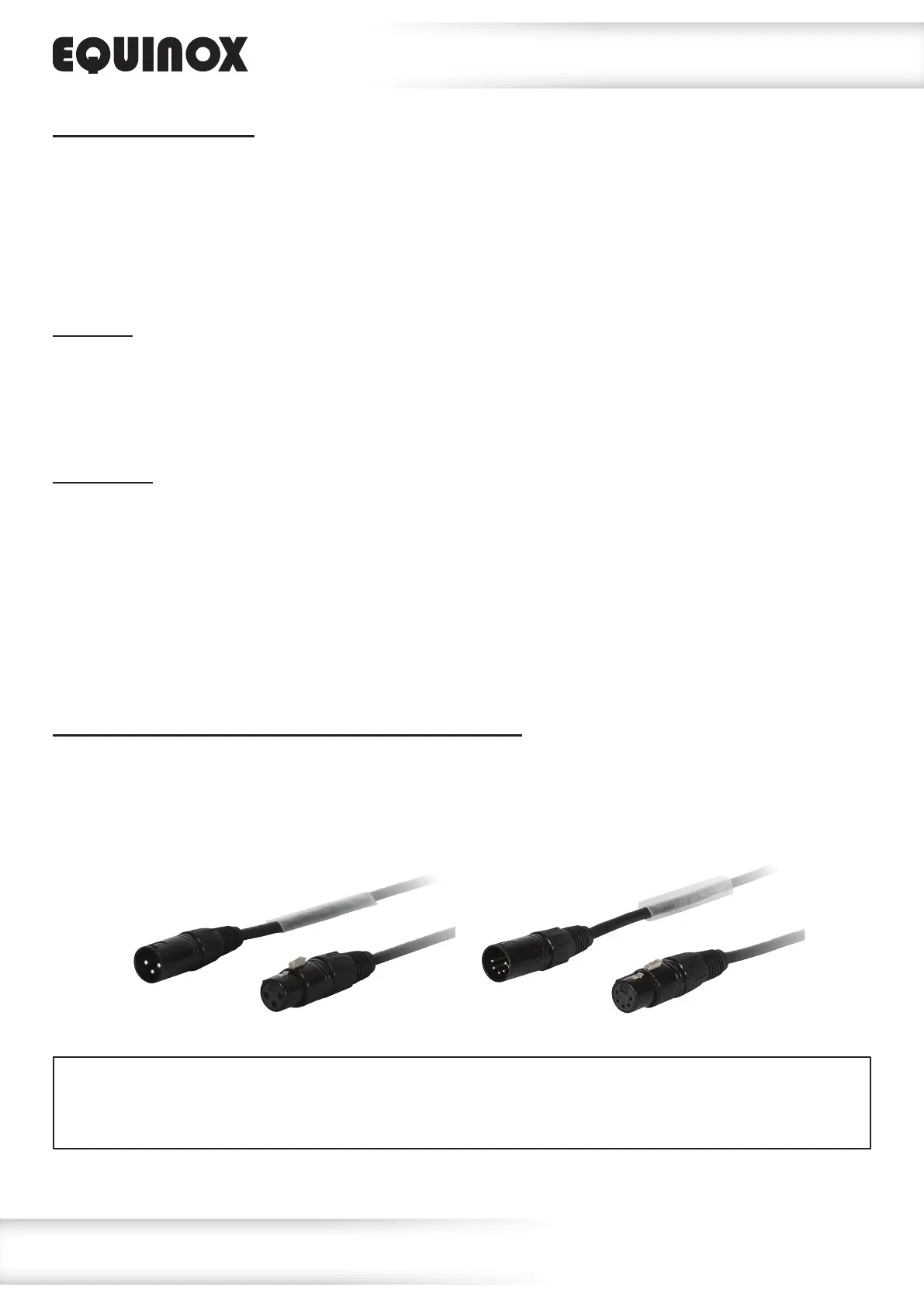
DATA cable (DMX cable) requirements (for DMX operation):
This xture can be controlled via DMX-512 protocol. The DMX address is set on the back of the unit.
Your unit requires either a standard 3-pin or 5-pin XLR connector for data input/output,
see images below.
Also remember that DMX cable must be daisy chained and cannot be split.
DMX setup
Further DMX cables can be purchased from all good sound and lighting suppliers or Prolight Concepts dealers.
Please quote:
CABL10 – 2m CABL11 – 5m CABL12 – 10m3-Pin:
CABL185 – 2m CABL187 – 5m CABL188 – 10m5-Pin: