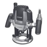
alignment as (shown in Fig 4). Afterwards turn scale
(2) to “0” (See Fig 4). Set step buffer (9) to the lowest
position, the buffer snaps-in noticeably.
Loosen wing screw (7), so that depth stop (6) can be
moved freely.
Release the clamping lever (3) by turning in clockwise
direction and slowly lower the router until the router
bit touches the surface of the workpiece. Lock the
router in position by turning the clamping lever in anti-
clockwise direction.
Press depth stop downwards until it touches the step
buffer (9). Adjust the depth stop (6) to the required
routing depth and tighten the wing screw (7). Release
the clamping lever and guide the router back up
again.
The coarse adjustment of the depth-of-cut should be
checked by a trial cut and corrected, if necessary.
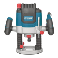
Fine Adjustment of the Depth-of-cut
After a trial cut, fine adjustment can be carried out
by turning the fine adjustment knob (1 scale mark
= 0.1 mm/1 rotation = 2.0 mm). The maximum
adjustment is approx. +/– 8 mm.
EXAMPLE: Slide router upwards again and measure
the depth-of-cut (set value = 10.0 mm; actual value
= 9.8 mm).
Lift up router and position guide plate (11) in such a
manner that the router can plunge freely without the
router bit touching the work-piece. Lower the router
again until the depth stop touches the step buffer
(9).
Afterwards set scale (2) to “0”.
Loosen wing screw.
With the fine adjustment (1), advance the depth-of-
cut in clockwise direction by 0.2 mm/
2 scale marks (= difference between required value
and actual value).
Retighten wing screw again.
Slide router upward again and check depth-of-cut by
carrying out another trial cut.
After setting the depth-of-cut, the position of the index
mark (26), on the depth stop should not be changed
anymore so that the currently adjusted setting can
always be read off the scale.
5. USAGE OF THE STEP BUFFER
a) Dividing the cutting procedure in several
steps
For deep cuts, it is recommended to carry out several
cuts, each with less material removal. By using the
Fig 4