is reached.
Guide router with projecting guide bush along the
template, applying light sideward pressure.
NOTE: The template must have a minimum thickness of
8 mm, due to the projecting height of the guide bush.
9. SHAPING OR MOULDING APPLICATIONS
For shaping or molding applications without the use
of a parallel guide, the router bit must be equipped
with a pilot or a ball bearing.
Lead the router sideward to the workpiece and allow
router bit to engage until the pilot or the ball bearing of
the router bit reach the corner of the workpiece being
machined. Guide the router alongside the workpiece
corner using both hands, ensuring proper seating of
the base plate. Too much pressure can damage the
edge of the workpiece.
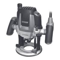
10. ROUTING WITH PARALLEL GUIDE (See Fig
7, 8)
Slide the parallel guide (21) with the guide rods (27)
into the base plate (10) and tighten at the required
distance with the locking screw for guide rod (12).
Guide the machine with uniform feed and sideward
pressure on the parallel guide (21) along the edge of
the workpiece.
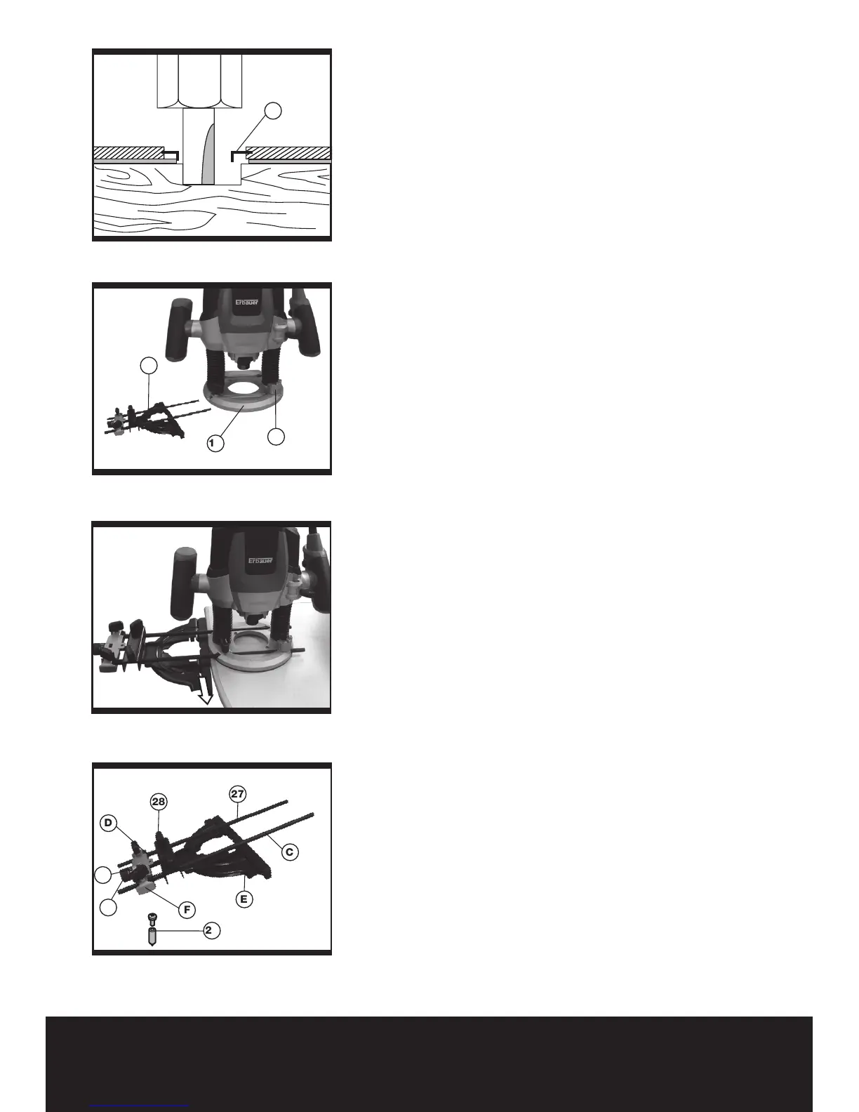
11. ROUTING CIRCULAR ARC PROFILES (See
Fig 9, 10,11)
To reassemble the router guide for use as a circle
guide (arc guide), follow below steps:
• Loosenrearwingknobs(28)andneadjustment
knob (A), spacer, and indicator (B), remove these
parts from guide rods (C).
• Loosen front knobs and guide base (E), remove
from the guide rods.
• Removesprings(D)fromguiderods.
• Reinstallneadjustmentguide(F)ontoguiderods,
rotate 180 degrees from normal position so that
circle guide hole faces away from the router.
• Insert the guide rods (C) into router base. For
maximum stability, make sure each rod goes
through both holes and protrudes out the other
side of the router base. At a maximum, the rods
must be inserted far enough into the router base
to ensure the rods are supported fully by the base
when the rods are clamped.
• Securelyfastentheroutertotherodsbytightening
the locking screws (12). The largest circles and
arcs can be made when the guide rods enter the
Fig 7
Fig 8
Fig 9
Fig 6