step buffer, the cutting process can be divided into
several steps.
Set the required depth-of-cut with the lowest step of
the step buffer. Afterwards, the higher steps can be
used for the last two cuts.
b) Pre-adjustment of varying depth-of-cuts
If several different depth-of-cuts are required for the
machining of a work-piece, these can also be preset
by using the step buffer.
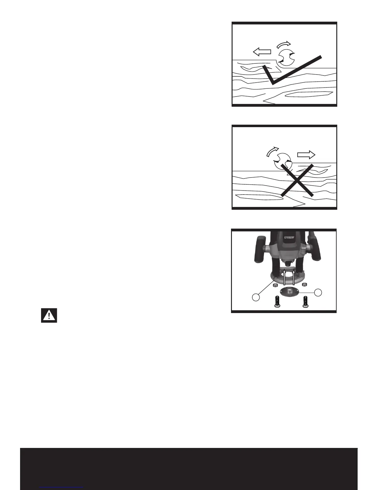
6. DIRECTION OF FEED (See Fig b, c)
The feed motion of the router must ALWAYS be
carried out against the rotation direction of the router
bit (See Fig b).
Do not route in the same direction of rotation as the
router bit, the router can become loose, preventing
control by the user.
7. MAKING A CUT
Note: Before starting work make sure workpiece is
firmly secured.
Place the base plate on the workpiece ensuring that
the bit is not in contact with the material to be cut.
Switch on the router and allow the bit to reach
maximum speed.
Release the clamping lever by turning in clockwise
direction and slowly lower the bit into the workpiece
surface,
keeping the base plate flush and advancing
smoothly until cutting is complete.
Keep the cutting pressure constant, taking care not
to overload the router so that the motor speed slows
excessively.
8. ROUTING WITH GUIDE BUSH (See Fig 6)
Warning: Choose a router bit with a smaller
diameter than the inner diameter of the
guide bush.
The guide bush (24) enables template and
pattern routing on work-pieces.
Place the guide bush over the hole in the
centre of the base plate, and align the two through
holes in the bottom of the base plate with the
countersunk holes in the guide bush. Fasten
the guide bush with the nuts and screws
provided.(See Fig 5).
Set the router with guide bush against the
template. Release the clamping lever by turning
in clockwise direction and slowly lower the router
toward the work-piece until the adjusted depth of cut