4(11)
Datum -
Date
Rev
Nr -
No.
Uppgjord (även faktaansvarig om annan) -
Prepared
(also subject responsible if other)
Dokansv/Godkänd -
Doc respons/Approved
Kontr -
Checked
File
1997-11-19 A
1531-DBC 214 01 Uen
INSTALLATION INSTRUCTIONS
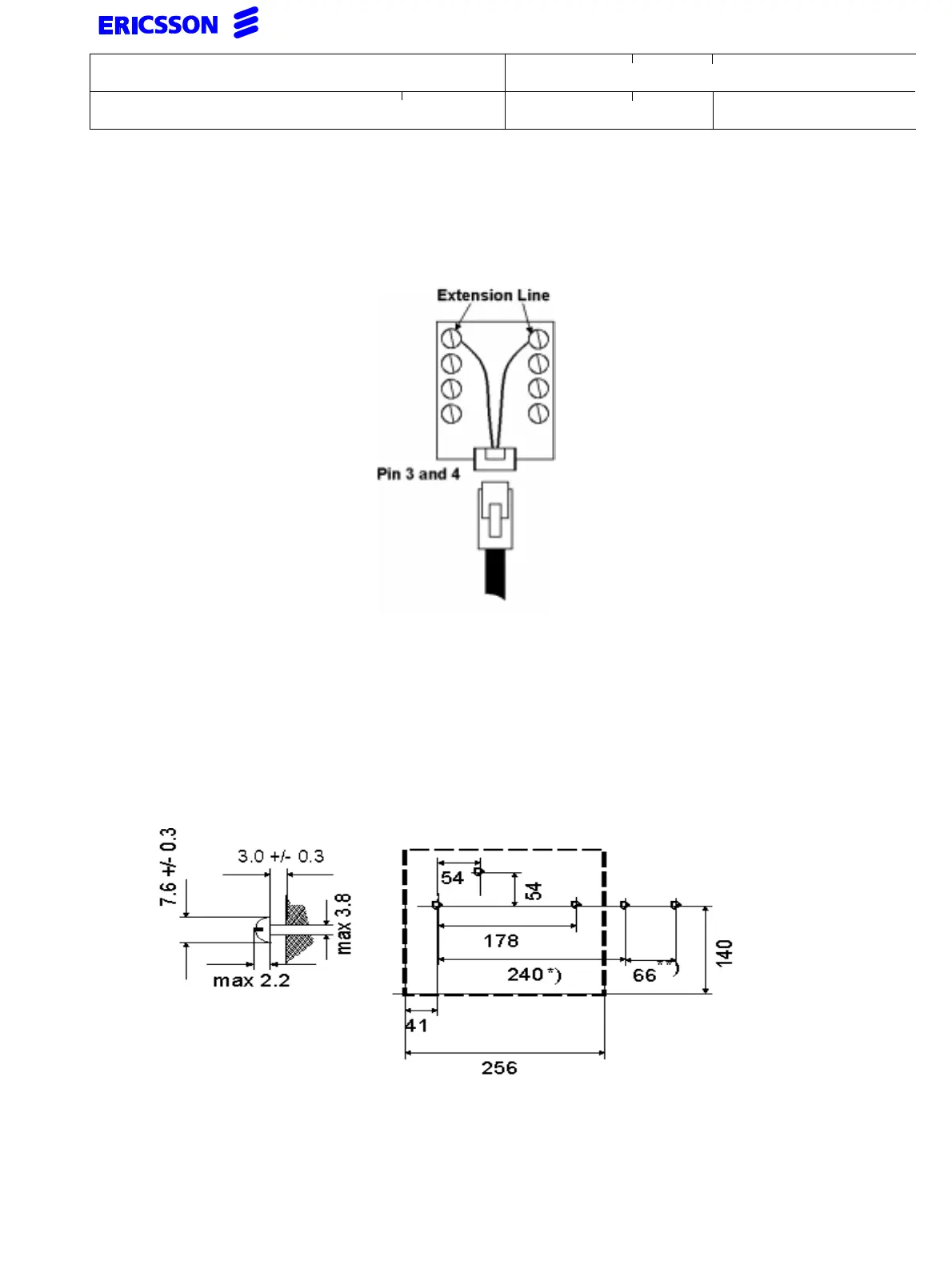
7.3 Connection to the extension line
The line cord shall be connected in one end to the wall box according to fig 7-1 and the other end
to the connector in the bottom of the set marked LINE.
Connection of extension line
7.4 Wall mounting
• Mount the two/three screws on the wall according to fig 7-2.
• Snap off and turn the hook around according to fig 7-3.
• If the adjustable foot consoles are mounted they must be removed.
• Mount the OPI on the screws.
Positions for screws (All distances in mm)
*) For DBY 409 No. 1
**) For DBY 409 No. 2,3 and 4 add 66mm