6(11)
Datum -
Date
Rev
Nr -
No.
Uppgjord (även faktaansvarig om annan) -
Prepared
(also subject responsible if other)
Dokansv/Godkänd -
Doc respons/Approved
Kontr -
Checked
File
1997-11-19 A
1531-DBC 214 01 Uen
INSTALLATION INSTRUCTIONS
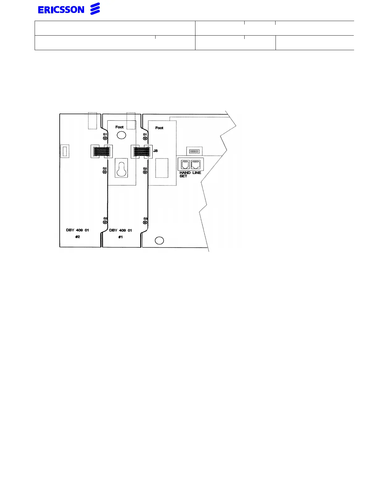
If a second DBY 409 01 is to be installed, do as follows
• The procedure above is repeated for the second DBY 409 01
• Move the foot to the second DBY 409 01
Rear view of DBC 214 01 with two DBY 409 01 connected.
8.2 Installation of key panel DBY 409 02 to OPI DBC 214 01
• Make necessary arrangements to avoid electrostatic discharges.
• Disconnect the OPI from the exchange
• Avoid if possible to touch the contacts
• Break off the blinder covering the contact J8
• Connect the cable from DBY 409 02 to contact J8
• Attach DBY 409 02 to DBC 214 01 and secure it with the three screws (S1, S2 and S3)
If additional DBY 409 02 are to be installed (maximum four), do as follows
• The procedure above is repeated for the second DBY 409 02
Snap the enclosed foot console to the last DBY 409 02 installed
Remove the blinder covering the contact J9
Connect the power supply unit (RES 141 305/2 or equal) to the DBY 409 02 closest to
the DBC 214 01 and then to the mains.
OPI type
DBC 214 01