Unit Description, RBS 2106 Climate Unit
Indicators, Buttons and Test Connector
P008423A
View of Backplane
C
C
U
F
A
U
L
T
O
P
E
R
A
TIO
N
H
E
A
T F
A
U
L
T
IN
T
.F
A
N
E
X
T
.F
AN
P
W
R
.F
A
U
L
T
E
P
C
B
U
S
A
C
T.
C
O
O
L-
F
A
N
A
C
T
.C
OO
L
T
E
S
T
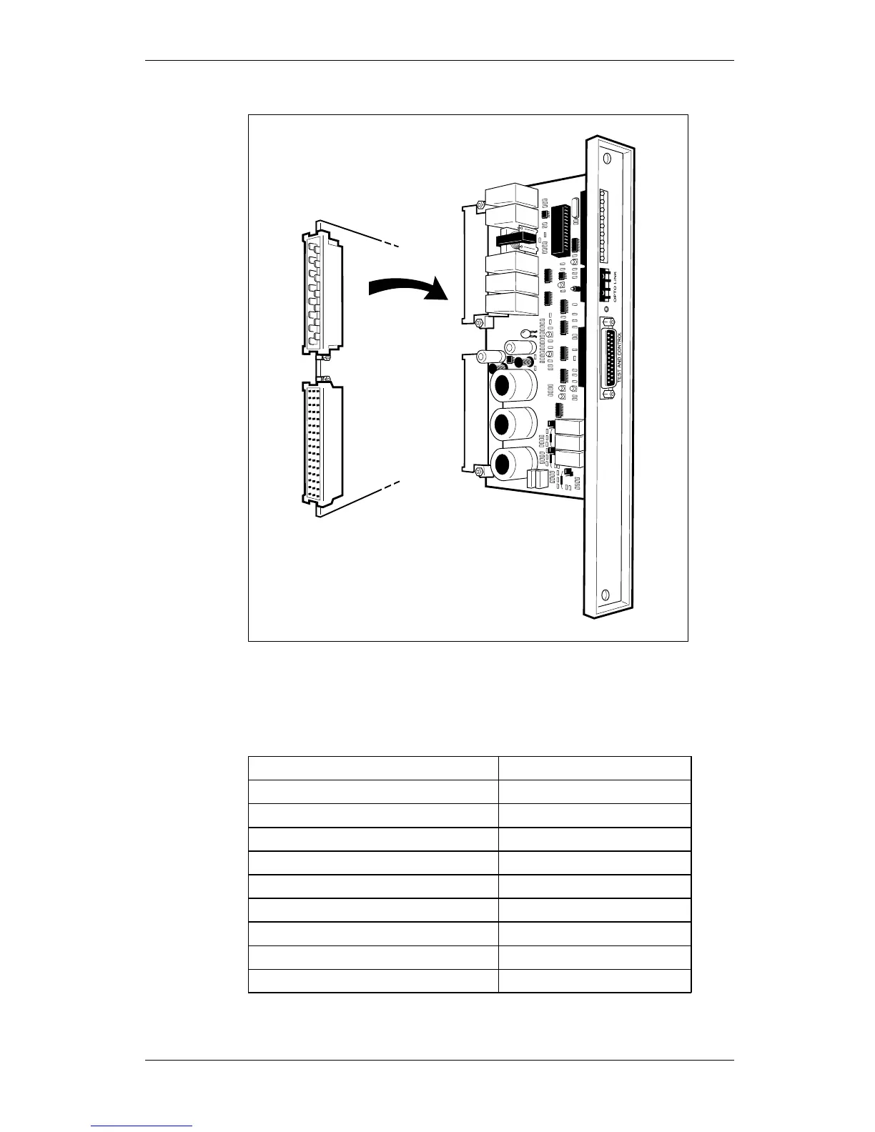
Figure 120 CCU
On the CCU front panel there are nine indicators (see the following
table), a test button and a test and general signal connector.
Table 144 Indicators
Indicator
Colour
CCU Fault Red
Operation Green
Heater fault Yellow
Heat exchanger internal fan fault Yellow
Heat exchanger external fan fault Yellow
Power fault
Yellow
EPC-bus fault
Yellow
Active cooler fan fault
Yellow
Active cooler fault
Yellow
220 (485)
EN/LZT 720 0008 P2A
2001-11-28
© Ericsson Radio Systems AB
— All Rights Reserved —
Preliminary