Channel Distribution Function
PCM
B
PCM
A
PCM
B
TS
1
2
3
4
5
6
7
PCM
A
RBS 1
RBS 2
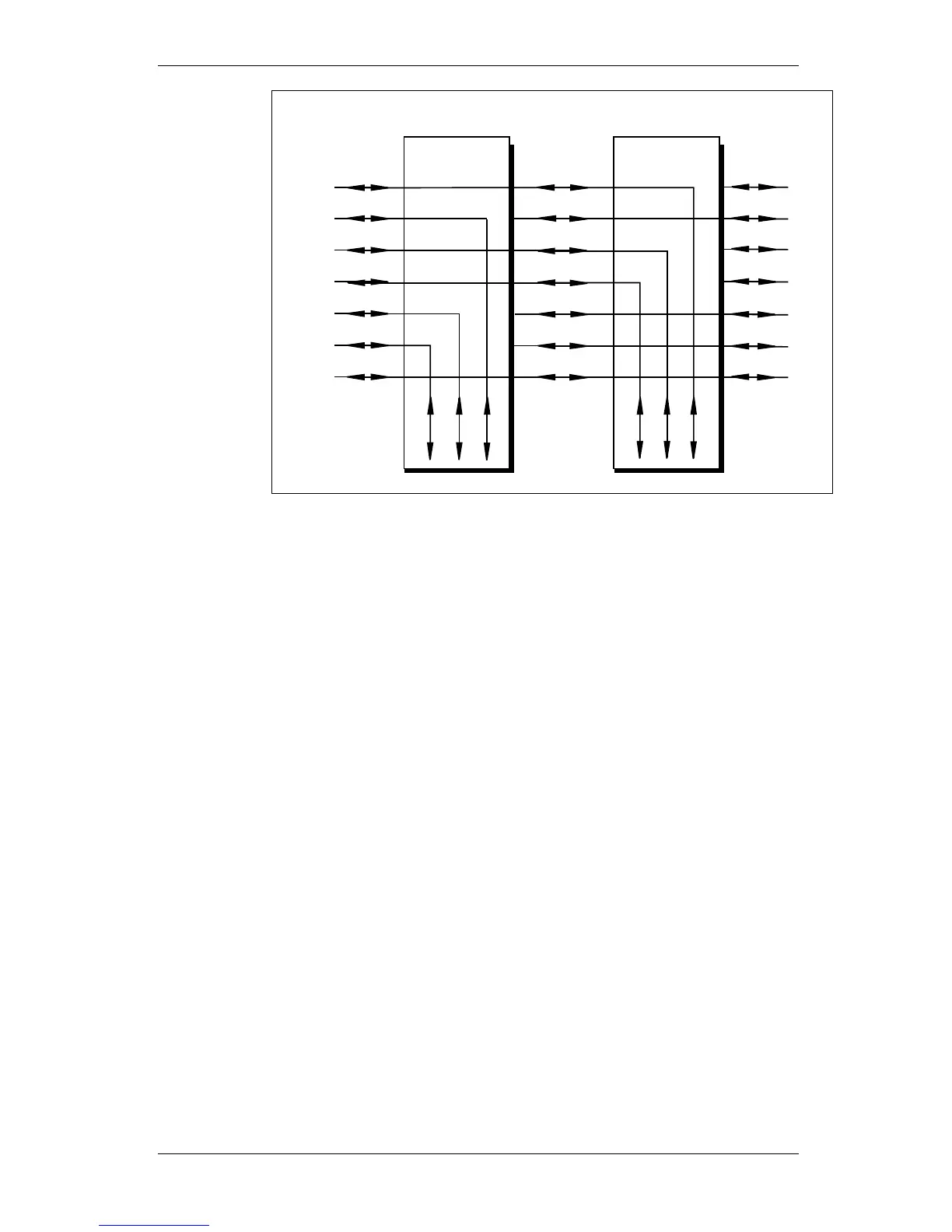
Figure 148 Multidrop example
All timeslots not used by the own RBS are transparently connected
between PCM A and PCM B.
The timeslots used by the RBS will be connected from PCM A to the
respective destination in the RBS. These timeslots will have valid idle
pattern transmitted on PCM B and incoming data on PCM B is ignored.
The RBS located at the end of the linear cascade chain transmits idle
pattern on all time slots not dedicated for the RBS itself on PCM-A
output.
When entering at least one of the alarm states LOF, LOS or AIS at
PCM-B input, the RBS is considered to be the RBS located at the end
of the linear cascade chain, presuming that PCM-A is not in loop mode.
It is considered to be so until the alarm state is left.
When entering loop mode (DXX line loop back) at PCM-B, the RBS
transmits idle pattern on all timeslots not dedicated for the RBS itself
on PCM-A output presuming that PCM-A is not in loop mode. Idle
pattern is transmitted until the loop mode on PCM-B is left.
When entering loop mode (DXX line loop back) at PCM-A, idle pattern
is transmitted on PCM-B output presuming that PCM-B is not in loop
mode. Idle pattern is transmitted until the loop mode on PCM-A is left.
Idle pattern is not transmitted on timeslot for the TN O&M channel.
The function is terminated when the parameter Network Topology is set
to not indicate multidrop.
56.3.5 Remote OMT Link
The function is initiated during restart of CMRU.
444 (485)
EN/LZT 720 0008 P2A
2001-11-28
© Ericsson Radio Systems AB
— All Rights Reserved —
Preliminary