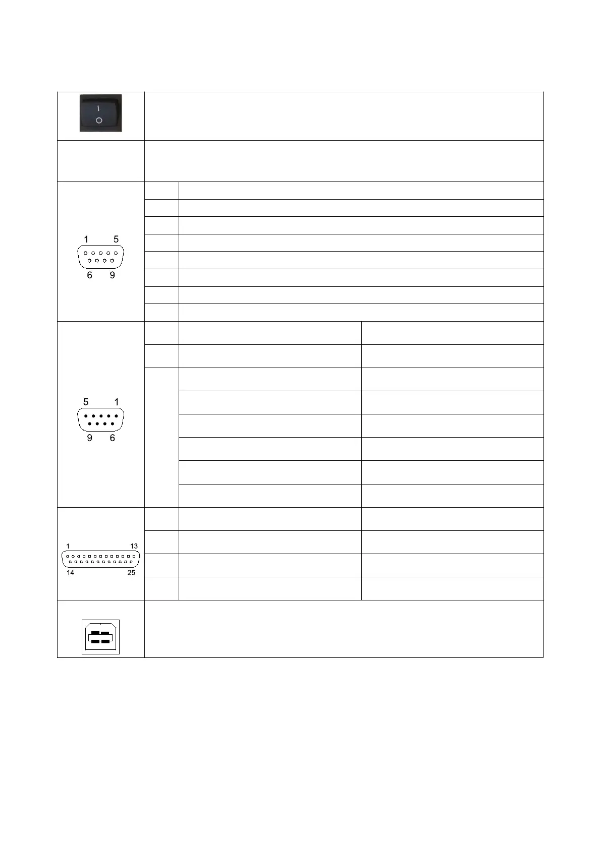
Connection Diagram
On/Off Switch
Power
85 – 264 VAC, 47 - 63 Hz, 0.25 A
Note: Make sure to connect the device to a grounded socket
Load Cell
Pin Explanation
1 - Signal
2 + Signal
3 - Sense (Note: Connect to - Excitaion if load cell sense not available)
4 + Sense (Note: Connect to + Excitaion if load cell sense not available)
5 Chassis
6 + Excitation
7 - Excitation
Remote Display
Pin Value ERTE Remote Display Connection
1, 2, 3 Not connected Not connected
4, 5,
6, 7,
8, 9
4 4
5 5
6 6
7 7
8 8
9 9
RS-232
Pin Value PC Connection
2 Tx 2
3 Rx 3
7
Gnd
5
USB
USB PC Connection
Note: USB driver must be downloaded and installed from www.erte.com.tr before the
cable is connected.
5