-- 2 5 --
dgb3d1ea
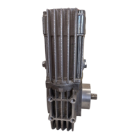
2.6 Components
A6 VEC comprises the following components:
1. Output shaft with bearing, tapered,
cylindrical or square stub.
2. Gearbox with M12 m ounting holes.
3. 4 bolts for attaching gearbox to motor housing.
4. Motor housing with m ounting holes.
Motor housing can be rotated 180˚ in relation
to gearbox.
5. Connection block for armature and stator
connections.
6. Cover (one either side) for commutator and
carbon brushes.
7. Ball bearing -- supports armature at commutator end.
8. M10 holes for attaching tachometer/pulse
generator.
9. Flange with M10 mounting holes.
10. Carbon brush with carrier.
11. Armature version as specified in
tables 1 and 2.
12. F ield winding (stator), can be configured
for97or60VDC.
13. Cooling fan.
14. Ball bearing -- supports armature at fan
end.
15. Toothed gear on motor shaft, ratio 8.2:1.
16. Worm gear, ratio as specified in
tables 1 and 2.
17. Worm wheel.
A6 VEC drive unit is prepared for fitting an angle sensor and tachometer sensor
(specification according to order).
GB