PEF
PTF
PEG
PEH
-- 3 0 --
dgb3d1ea
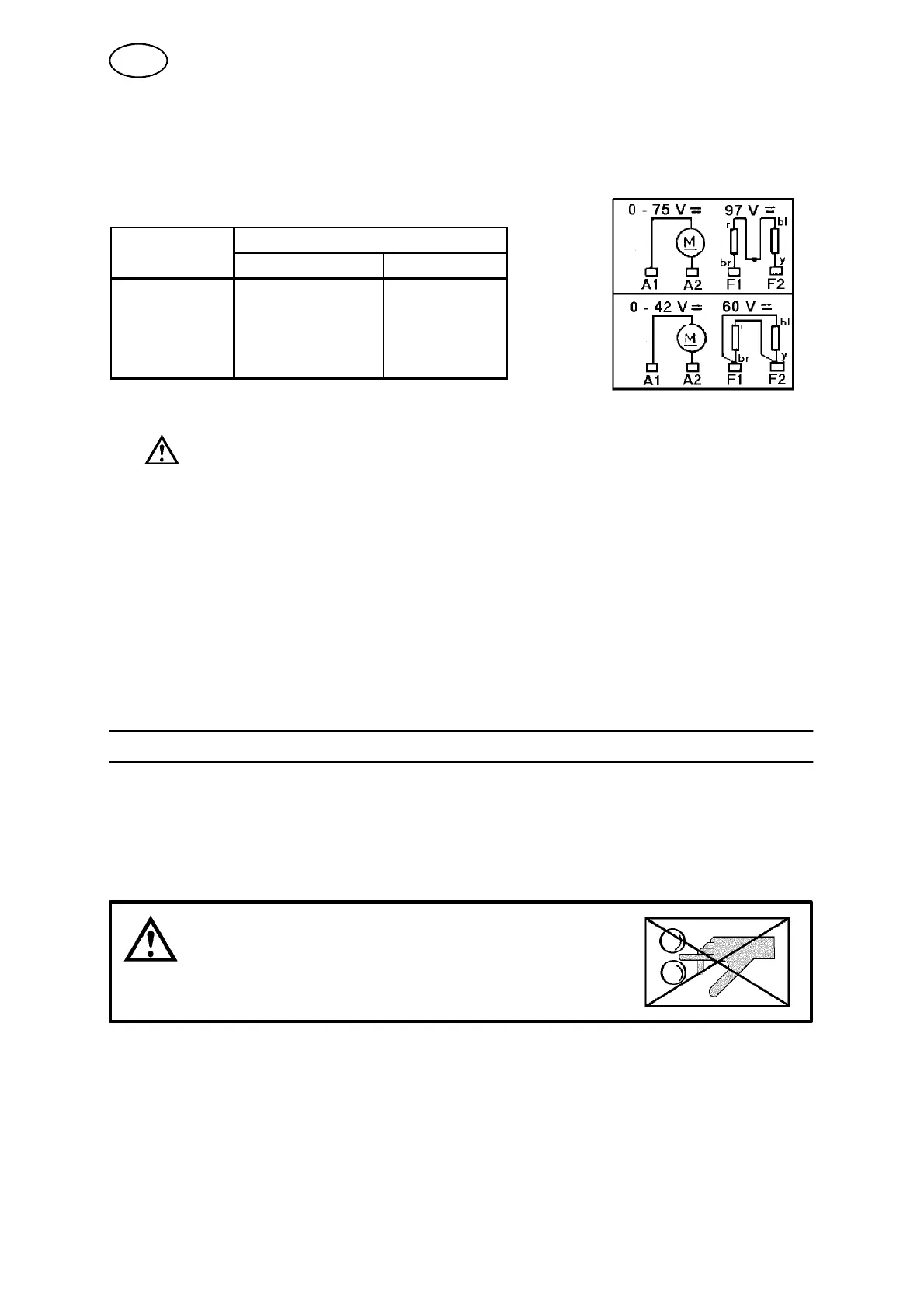
3.3 Connection instructions
To avoid interference problems the connection cables should be screened.
Table 6
Colour of wire Version
New Older
Armature Green Black
Armature White Red
Field F1 Brown (also blue) Yellow
Field F2 Yellow (also red) Blue
1. Make sure that:
S the field is correctly wired, in parallel or in series
S the regulator is correctly wired for the chosen armature and speed (see
manual for the regulator in question).
2. The direction of rotation of the motor can be changed if necessary by switching
the polarity of the rotor
3. Various types of sensors can be connected to the motor, see Accessories.
4. See also dimension drawing on page 32.
4 OPERATION
4.1 General
General safety regulations for the handling of the equipment appear from
page 19. Read through before you start using the equipment!
WARNING!
Rotating parts can cause injury, take great care.
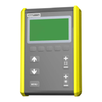
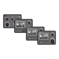
Set the desired speed manually using any of the regulators PEG1, PEH, PEF or PTF.
All per sonnel who work with the A6 VEC must be thoroughly familiar with:
S the operation of the unit
S the function of the unit
S all relevant safety precautions.
GB