-- 2 9 --
dgb3d1ea
3 INSTALLATION
3.1 General
The installation shall be executed by a p rofessional.
3.2 Assembly instructions
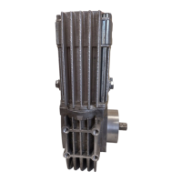
1. Install the A6 VEC in the required position. Threaded holes are provided at both
ends and on the sides of the motor and gearbox for this purpose and for the
attachment of external components ( see dimension drawing).
The motor must be securely bolted to a rigid surface to prevent the unit or other
attached components from working loose.
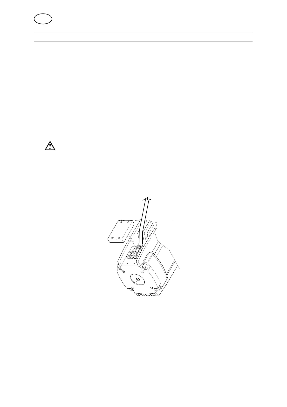
2. Check that A6 VEC is wired for the correct voltage.
The VEC motor can be connected to various supply voltages, see table below.
Connect the cable to the 4--pole connection block marked F1 and F2 for field
supply and A1 and A2 for armature supply.
The cable is supported by the cover protecting the connection blocks, see figure
below.
For connection to regulator PEG1 and PEH
S Armature voltage 42 V DC
S Field voltage 60 V DC, connection in parallel
For connection to regulator PEF and PTF
S Armature voltage 75 V DC
S Field voltage 97 V DC, connection in series
GB