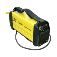
Do you have a question about the ESAB Caddy Tig 2200i TA33 and is the answer not in the manual?
Details the power source's modular structure and inverter principle of operation.
Lists and describes all components used within the wiring diagrams and modules.
Explains the operator's control panel and display for setting welding data.
Details the function of the power supply board and its different hardware versions.
Outlines the primary circuit configuration and operation of the 2AP1 power supply board.
Explains the secondary circuit and its various voltage outputs from the 2AP1 board.
Illustrates the physical placement of components on the 2AP1 power supply board.
Introduces the 10AP1 TIG board and its connection to the mains voltage supply.
Explains the HF generator's function for initiating the welding arc.
Shows the physical placement of components on the 10AP1 TIG board.
Details the power board's rectifier, charging, PFC circuits, and gate drivers.
Explains the gate driver transformer for galvanic isolation of drive circuits.
Describes the switching transistors integrated within the 15AP1 semiconductor module.
Shows the physical placement of components on the 15AP1 power board.
Describes the secondary board fitted onto the main transformer 15TM1.
Explains the function of the 15D1 diode module and L1 inductor in the 15AP2 board.
Describes the processor's role in monitoring and controlling power source functions.
Describes processor control of welding current based on input data and arc voltage.
| Mains Voltage | 230 V |
|---|---|
| Frequency | 50/60 Hz |
| Welding Current Range | 5 - 220 A |
| Setting Range TIG DC | 5 - 220 A |
| Setting Range MMA DC | 10 - 220 A |
| Output Current Range (TIG) | 5 - 220 A |
| Output Current Range (MMA) | 10 - 220 A |
| Protection Class | IP 23 |
| Dimensions | 418 x 188 x 345 mm |
| Rated Input Current | 16 A |
| Power Supply | Single phase |
