Do you have a question about the ESAB Caddy Tig 1500i TA34 and is the answer not in the manual?
Explains the function of the power supply board in filtering mains and generating voltages.
Describes the TIG board's function and its connection to mains voltage.
Explains the HF generator's operation and voltage characteristics for ignition.
Details the power module's function, converter type, and integrated components.
Describes the PFC circuit's role in maintaining sinusoidal mains current and intermediate voltage.
Describes the secondary board, its components, and their functions.
Explains the control board's role in monitoring, controlling, and handling various functions.
Explains the CAN bus communication system used for inter-unit communication.
Lists points to check for CAN bus communication problems.
Details the thermal overload switches and their operation.
Explains the shunt's function in measuring current and its connection.
Describes the circuit for measuring and scaling arc voltage for the processor.
Details fault codes for the power source and welding data unit.
Provides instructions and measuring points for testing the 15AP1 semiconductor module.
Details how to check rectifier and freewheel diodes on the 15AP2 board.
Explains how to check gate pulses for proper operation.
Recommends soft starting after component replacement to prevent damage.
| Brand | ESAB |
|---|---|
| Model | Caddy Tig 1500i TA34 |
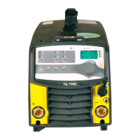
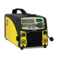
| Category | Welding System |
| Language | English |