EasyManua.ls Logo

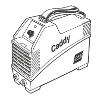
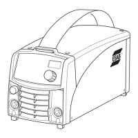
ESAB Caddy 130 User Manual

ESAB Caddy 130
36 pages
To Next Page IconTo Next Page
Page #1 background imageLoading...
Page #1 background image
0740 800 043
Valid for serial no. 301--xxx--xxxx to 220--xxx--xxxx040906
LHN 130/140/200
Caddy 130/140/200
cmha2p00
Service manual
Question and Answer IconNeed help?

Do you have a question about the ESAB Caddy 130 and is the answer not in the manual?

ESAB Caddy 130 Specifications

General IconGeneral
Fuse Size16 A
Enclosure ClassIP23
Rated Input Current16 A
Input Voltage230 V
Welding ProcessMMA

Summary

Component Description

Circuit Boards (AP01-AP05)

Description of main circuit boards and their functions.

Passive Components (C04-C06, L01-L07, RV01)

Description of capacitors, inductors, and varistors.

Transformers, Switches, and Protection

Description of transformers, switches, potentiometers, shunts, and cutouts.

Diodes, LEDs, and Connectors

Description of diodes, LEDs, terminal blocks, and connectors.

Wiring Diagram LHN 130

Wiring Diagram LHN 140 (Before Serial No. 011-xxx-xxxx)

Wiring Diagram LHN 140 (Serial No. 011-xxx-xxxx and 220-xxx-xxxx)

Wiring Diagram LHN 200 (Before Serial No. 011-xxx-xxxx)

Wiring Diagram LHN 200 (Serial No. 011-xxx-xxxx and 220-xxx-xxxx)

Component Positions, Circuit Board AP01

AP01 (Before Serial No. 220-xxx-xxxx)

Component layout for circuit board AP01 before serial number 220-xxx-xxxx.

AP01 (From Serial No. 220-xxx-xxxx)

Component layout for circuit board AP01 from serial number 220-xxx-xxxx.

Description of Operation, Circuit Board AP01

Power Supply and Thermal Shutdown

Description of AP01 power supply and thermal shutdown circuits.

Voltage, Current, and Arc Control

AP01 circuits for voltage detection, current sensing, and arc limitation.

Current Reference and Control Amplifier

AP01 circuits for current reference, control amplifier, and PWM.

Gate Circuit Operation

Operation of the AP01 gate circuit for MOSFET transistors.

Checking Gate Pulses

Circuit Diagram, Circuit Board AP02

Component Positions, Circuit Board AP02

Circuit Diagram, Circuit Board AP03

Component Positions, Circuit Board AP03

MOS Tester

Soft Starting Procedure

Assembly and Disassembly

Rear Panel and Casing Removal

Steps for removing the rear panel and casing of the unit.

Front Panel and Rectifier Unit Removal

Steps for removing front panel and rectifier unit.

Transistor Board Removal and Refitting

Procedures for removing and refitting transistor circuit boards.

Fitting the Main Transformer TC02

Load Characteristics

Technical Data

Installation Instructions

Operation

Front Panel Controls

Description of front panel controls and indicators for LHN 130/140/200.

Welding Modes

Guidance on coated electrode and TIG welding.

Operational Safety

General safety precautions during operation.

Maintenance Procedures

Spare Parts Information

Related product manuals