-- 2 8 --
cmha2de1
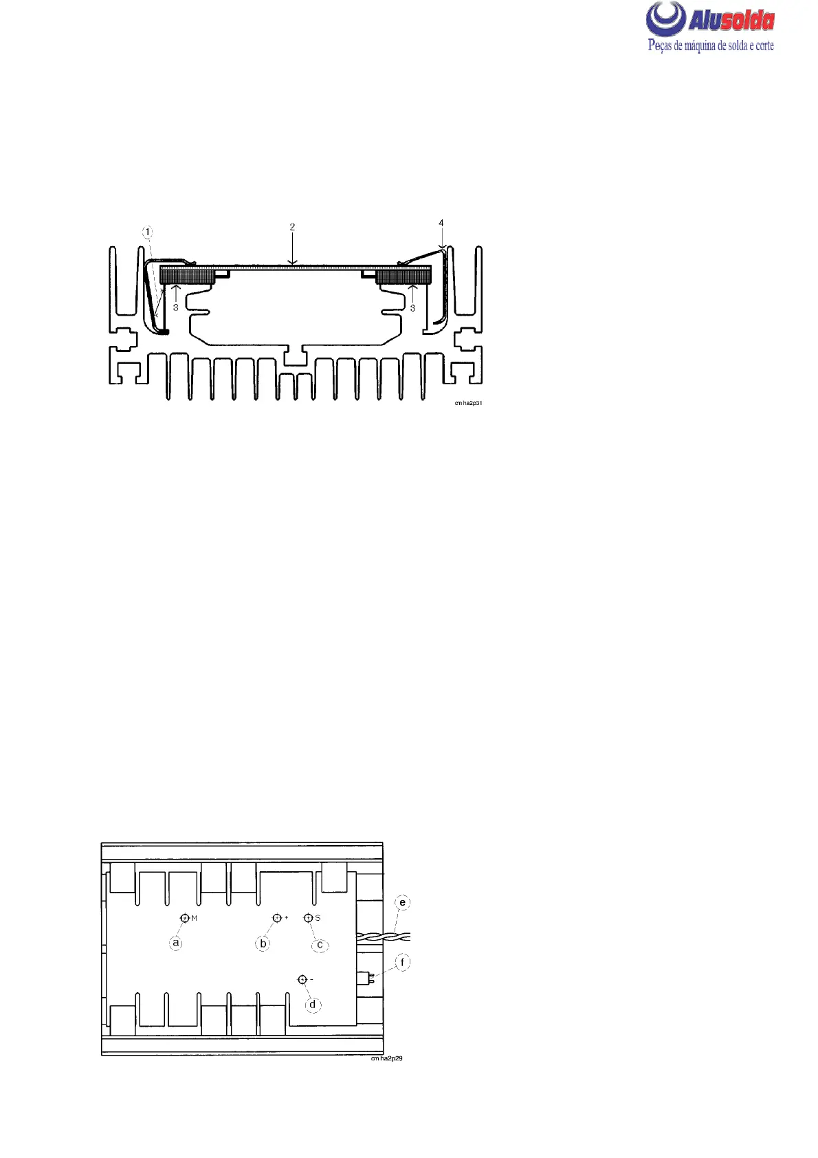
REMOVAL OF TRANSISTOR CIRCUIT BOARDS AP02 AND AP03
S Remove the rear panel and casing.
S Remove all wires and busbars connected to the board.
S Remove the springs that hold the board (2) in position by prising them off with a
screwdriver (1) between the cooling flange and the spring.
Removal/refitting of transistor circuit board
REFITTING THE TRANSISTOR CIRCUIT BOARD
S When replacing the transistor circuit board, both boards must always be replaced and
new springs must be fitted.
S Clean the contact surface (3) of the heat sink with extremely fine abrasive paper.
S Apply a thin film of contact oil (see item 555 / 904 in the spare parts list) to the contact
surfaces.
S Place the circuit board (2) on the cooling fins. Secure first one spring on each side of the
board by pressing the spring down with a screwdriver (4). Then secure the remaining
springs.
NOTE: The springs must be fitted where there are components that are to be in contact
with the heath sink. Due to a change to transistors with higher current rating, there might
be less transistors on the spare part board than on the original board.
S When fitting cable lugs and busbars to the boards, it is important that the washers are
fitted in the correct order. Start by placing the lug on the foil, and then fit a flat washer, a
spring washer and finally the screw.
Connections to circuit board AP03
a
LHN 130/140: not connected
LHN 200: wire 031 to the connection
between C02 and C03
b
LHN 130/140: busbar to positive on C02
LHN 200: busbar to positve on C03
c
Busbar connected to negative on C02
d
LHN 130/140: wire 024 from inductor L03
LHN 200: wire 013 from negative of V02
e
Gate connection from circuit board AP01
f
Connector XS08 from transformer TC02