cmha2p28
-- 2 7 --cmha2de1
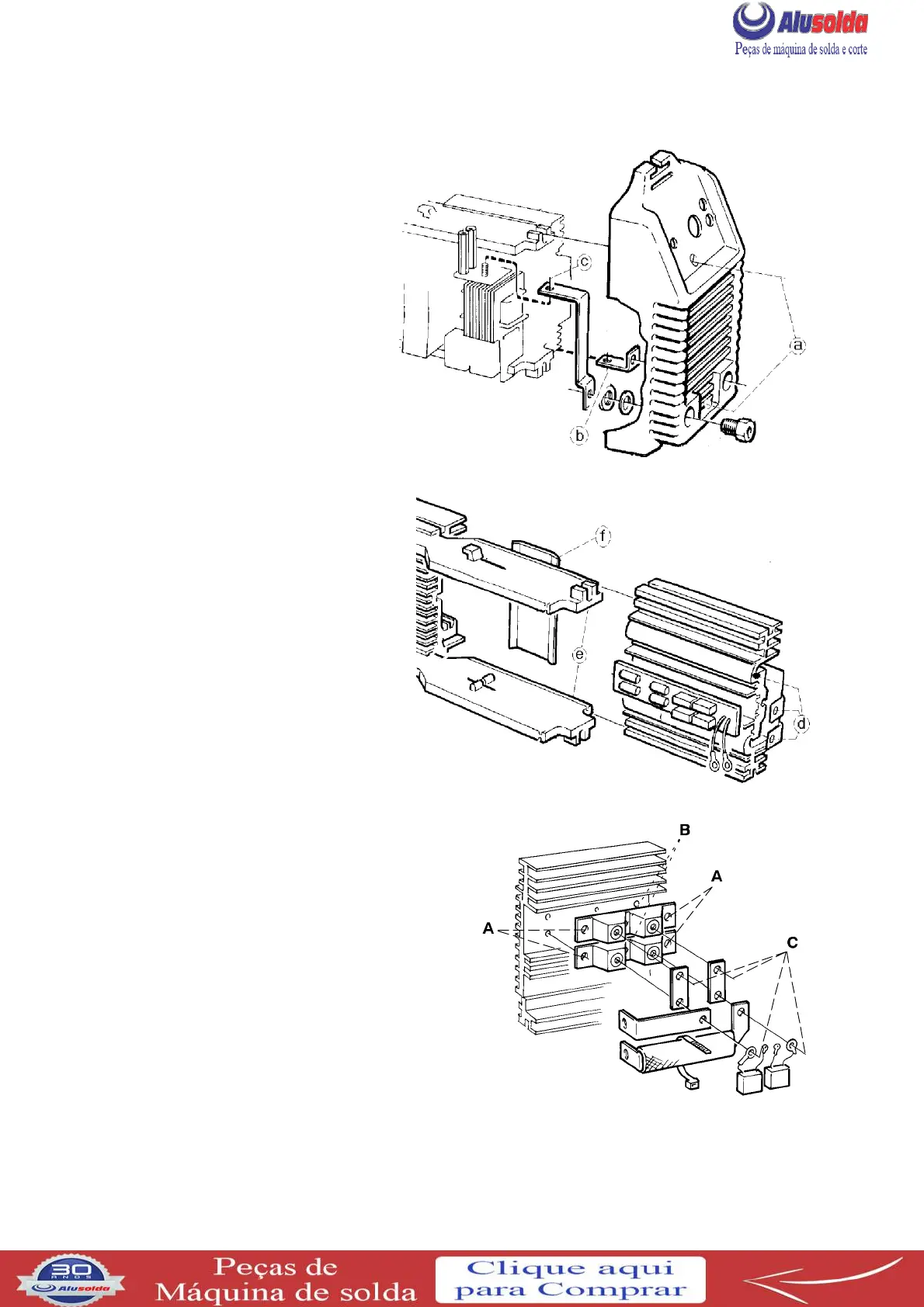
REMOVAL OF FRONT PANEL
S Remove the rear panel and
casing.
Remove screws (a).
S Remove the positive busbar
from the rectifier unit.
Screw (b) is accessible from
beneath the machine.
S Remove nut (c) and remove
the negative busbar from
the shunt.
S Remove connectors XS10 and
XS03 from circuit board
AP01.
REMOVAL OF THE RECTIFIER UNIT
S Remove the rear panel, casing
and front panel.
S Remove screws (d).
S Pull out the rectifier unit.
FITTING THE RECTIFIER UNIT
S Position insulation sheet (f) against
transformer TC02 and slide the
rectifier unit into the guides (e).
FITTING THE DIODE MODULE
Valid from serial number 628--xxx--xxxx.
S Clean the contact surface of the heat sink
with extremely fine abrasive paper.
S Apply a thin film of contact oil (see item
555 / 904 in the spare parts list) to the
contact surfaces.
S Fit the diode modules and tighten the screws
A (M6) to a torque of 6 Nm. Tighten the
screws B (M4) to a torque of 1 Nm.
The screws C (1/4” 20UNC2B) are to be
tightened to a torque of 6 Nm.
From serial number 011--xxx--xxxx the diode modules are different connected compared to
the picture above: see the spare parts list. The fitting procedure for the modules is however
the same as described above.