-- 2 3 --cmha2de1
D5 Back--emf protection diode (squelch diode) for main transformer TC02 when
the transistors turn off.
Q1--Q8 MOSFET transistors. These require a special instrument
(see MOS TESTER on page 24 for testing.
Due to a change to transistors with higher current rating, the circuit board may
have one transistor less than specified in the diagram above.
R21 Charging resistor, 12Ω, 10W, for buffer capacitor C02 (C03). When energising
the power unit, pulses from control circuit board AP01 ar e delayed by 300 ms to
allow the buffer capacitor to charge.
R26 Discharge resistor f or buffer capacitor C03. This capacitor is fitted only in the
LHN 200. Discharge time for the capacitor, after turning off the mains power
supply, is about two minutes.
R27 Discharge resistor for buffer capacitor C02. After turning off mains power
supply, discharge time for the capacitor is about two minutes.
TY1 Thyristor for shunting charging resistor R21 when the machine is loaded.
If T Y1 did not conduct, resistor R21 would burn out when the unit is on load.
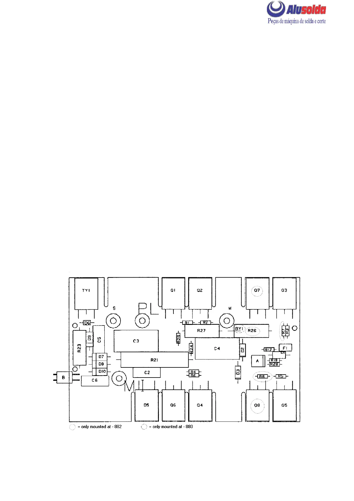
COMPONENT POSITIONS, CIRCUIT BOARD AP03
cmha2e09