-- 2 2 --
cmha2de1
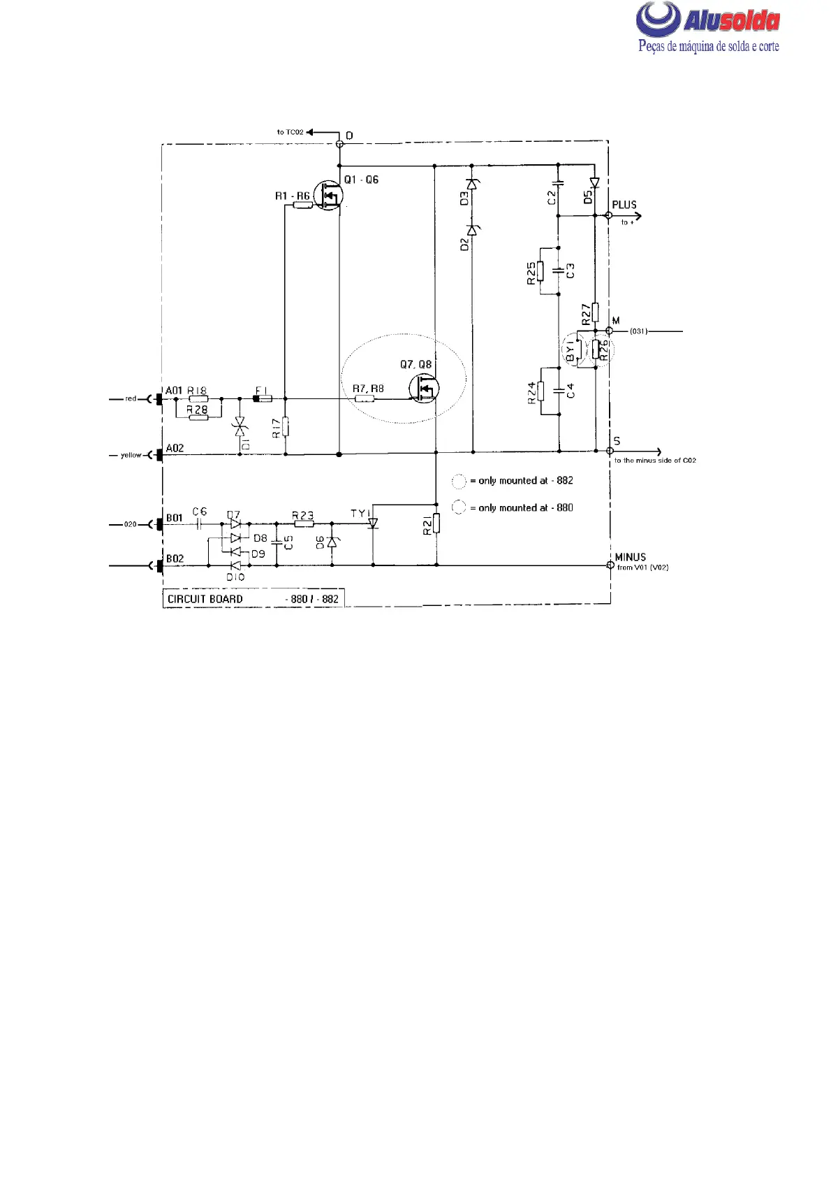
CIRCUIT DIAGRAM, CIRCUIT BOARD AP03
cmha2e08
AP03 (NEGATIVE) CIRCUIT BOARD 481 848 --880 / --882 / --889
The --880 variant is used in the LHN 140, the --882 variant in the LHN 200 and the --889
variant in LHN 130.
The --889 variant has the same design as the --880 variant, the only difference is that transistor
Q6 isn’t mounted at the --889 variant.
Individual transistors must not be replaced: if the circuit board is faulty, it must be replaced
in its entirety. In addition, circuit board AP02 must also be replaced.
See on page 28 for instructions on removing and fitting the circuit board.
A01,A02 Connections A01 -- A02 are for the gate pulses from circuit board AP01.
B01,B02 When the machine is loaded, pulses from a trigger pulse winding on main
transformer TC02 are supplied to connections B01 and B02, for use as gate
pulses in controlling thyristor TY1.
D1--D3 Transient voltage protection.