-- 1 4 --
cmha2de1
DESCRIPTION OF OPERATION, CIRCUIT BOARD AP01
This description refers to the wiring diagrams on pages 7--11 and to the component position
diagrams on pages 12 and 13. Only those items connected to the circuit board inputs and
outputs are described here. If the circuit board is faulty, it must be replaced.
There are three versions of the circuit board, this description applies to all versions. T he
circuit boards are fully interchangeable.
After r eplacing the circuit board, the machine must be soft--started, as described on page 25.
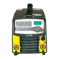
1 Power supply
Rectifier bridge D1-- D4 is supplied at 20.5 V from transformer T C01. T he rectified voltage
is stabilised by voltage regulator VR1 to +20 ±1 V. All circuits on the circuit board except
the current reference (6) and the gate circuit (9) are supplied f rom VR1.
Connections A05 -- A06 supply 26 V DC ±2.5 V to the cooling fan.
The fan is not the same in LHN 130 as in LHN 140/200, see the spare parts list.
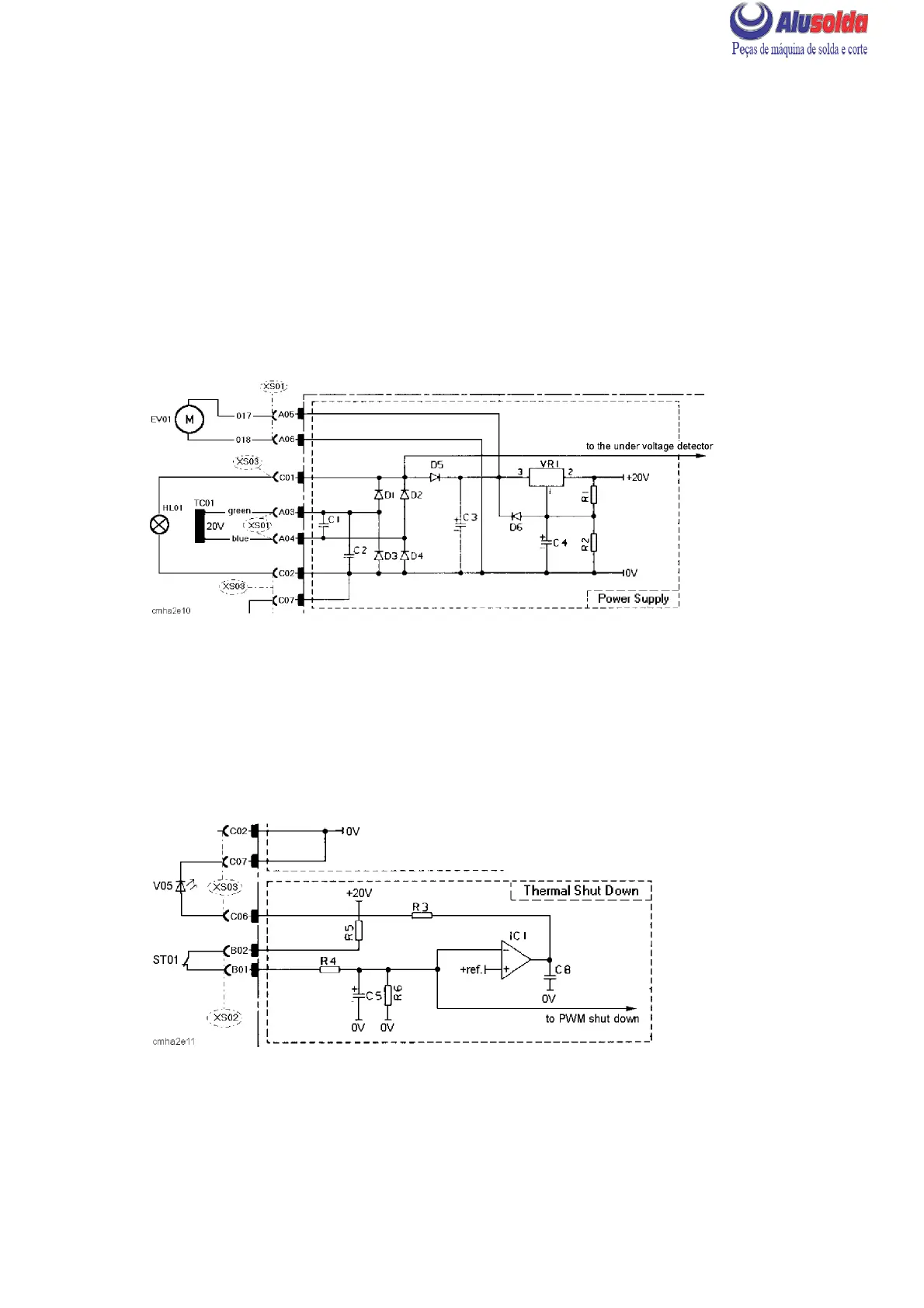
2 Thermal shutdown
This circuit interrupts the gate pulses from the pulse width modulator if the machine is
overloaded. When it has not operated due to high temperature, the thermal overload cutout
normally short--circuits inputs B01 and B02. If the cutout contact opens, IC1 lights LED
V05 and the pulse width modulator (8) blocks the gate pulses. See also ST01 in the
component description.
The reference voltage to IC1, +ref., is generated by IC3: see page 17.