-- 2 0 --
cmha2de1
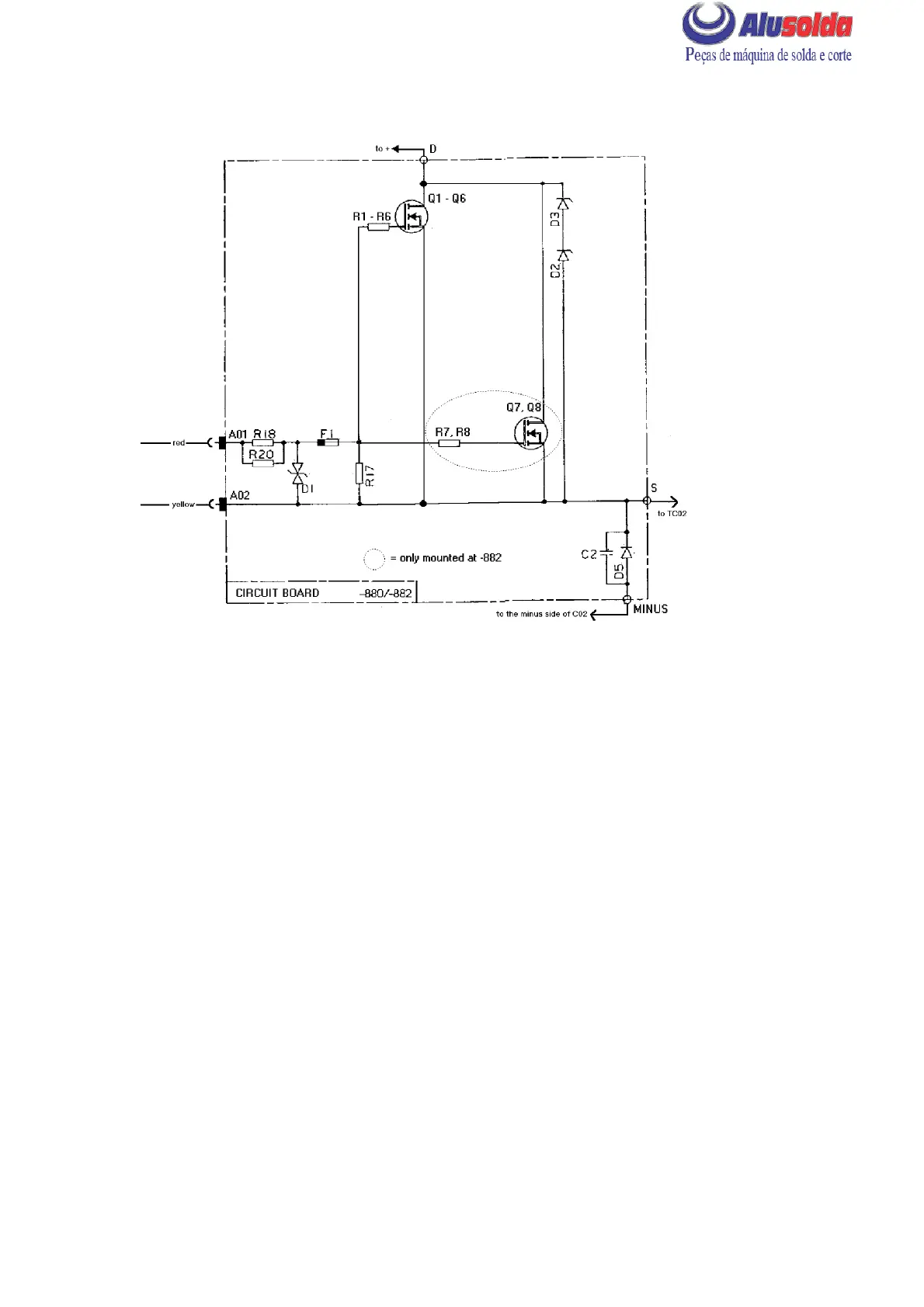
CIRCUIT DIAGRAM, CIRCUIT BOARD AP02
cmha2e06
AP02 (POSITIVE) CIRCUIT BOARD 481 803 --880 / --882 / --889
The --880 variant is used in the LHN 140, the --882 variant in the LHN 200 and the --889
variant in LHN 130.
The --889 variant has the same design as the --880 variant, the only difference is that transistor
Q6 isn’t mounted at the --889 variant.
Individual transistors must not be replaced: if the circuit board is faulty, it must be replaced
in its entirety. In addition, circuit board AP03 must also be replaced.
Instructions on removing and fitting the circuit boar d are to be found on page 28.
A01,A02 Connections A01 -- A02 are for the gate pulses from circuit board AP01.
D1--D3 Transient voltage protection.
D5 Back--emf protection diode (squelch diode) for main transformer TC02 when
the transistors turn off.
F1 Fuse, for protection of circuit board AP01 if circuit boar d AP02 f ails.
Q1--Q8 MOSFET transistors. These require a special instrument
(see MOS TESTER on page 24) for testing.
Due to a change to transistors with higher current rating, the circuit board may
have one transistor less than specified in the diagram above.