EasyManua.ls Logo

ESAB ET 200iP Pro - User Manual

ESAB ET 200iP Pro
26 pages
Print Icon
To Next Page IconTo Next Page
Loading...
Rogue
Instruction manual
0463 712 101 GB 20210224
Valid for: HA027-xxxx-xxxx
ET 200iP PRO

Questions and Answers

Summary

SAFETY

Meaning of symbols

Explains hazard warning symbols used in the manual.

Safety precautions

Outlines essential safety measures for operating personnel and the workplace.

Personal safety equipment

Details required personal protective equipment for welding operations.

General precautions

Lists important safety steps and considerations for safe operation.

ELECTRIC SHOCK - Can kill

Warns about the lethal danger of electric shock and how to prevent it.

ELECTRIC AND MAGNETIC FIELDS - Can be dangerous to health

Discusses health risks from EMF and mitigation procedures for welders.

FUMES AND GASES - Can be dangerous to health

Addresses health hazards from welding fumes and gases, recommending ventilation.

ARC RAYS - Can injure eyes and burn skin

Explains the risk of eye/skin injury from arc rays and protective measures.

NOISE - Excessive noise can damage hearing

Highlights the danger of excessive noise to hearing and suggests protection.

MOVING PARTS - Can cause injuries

Warns about potential injuries from moving parts and how to avoid them.

FIRE HAZARD

Identifies fire risks associated with welding operations and necessary precautions.

HOT SURFACE - Parts can burn

Alerts users to hot surfaces on the equipment and precautions against burns.

MALFUNCTION - Call for expert assistance in the event of malfunction.

Advises seeking expert help for equipment malfunctions to prevent further damage or injury.

INTRODUCTION

Equipment

Lists the components included with the Rogue ET 200iP PRO welding power source.

TECHNICAL DATA

INSTALLATION

Location

Provides guidelines for positioning the welding power source for optimal cooling.

Lifting instructions

Details safe procedures for lifting and moving the welding power source.

Mains supply

Explains the requirements and procedures for connecting the power source to the mains supply.

OPERATION

Overview

Provides a general introduction to the operation of the welding power source.

Connections and control devices

Identifies and explains the various connections and control elements on the front panel.

Connecting welding and return cables

Describes how to properly connect welding and return cables to the power source.

Turning the power on;off

Details the procedure for switching the welding power source on and off.

Fan control

Explains the automatic fan control feature for cooling and power saving.

Thermal protection

Describes the built-in thermal protection system and its indicators.

Functions and symbols

Explains the different welding functions and associated symbols for operation.

Hot start

Describes the Hot Start function for MMA welding to improve arc initiation.

TIG welding

Explains the process and requirements for performing TIG welding with the unit.

HF start

Details the High Frequency (HF) start method for initiating the TIG arc.

Voltage Reduction Device (VRD)

Explains the VRD function for reducing open-circuit voltage for safety.

Setting panel

Describes the components and operation of the equipment's setting panel.

Remote control

Explains how to connect and use the remote control for the power source.

MAINTENANCE

Routine maintenance

Outlines a schedule for regular maintenance tasks to ensure performance.

Cleaning instruction

Provides detailed steps and precautions for cleaning the welding power source.

TROUBLESHOOTING

ORDERING SPARE PARTS

DIAGRAM

ORDERING NUMBERS

ACCESSORIES

Overview

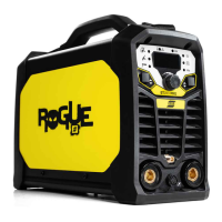
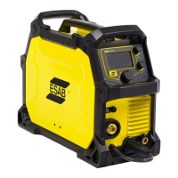
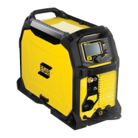
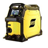
The ESAB Rogue ET 200iP PRO is an inverter-based power source designed for Manual Metal Arc (MMA) and Tungsten Inert Gas (TIG) welding, including High Frequency (HF) TIG welding. This robust and versatile machine is suitable for industrial use, offering a range of features for efficient and safe welding operations.

Function Description

The Rogue ET 200iP PRO serves as a welding power source, converting input electrical power into a suitable output for arc welding. It supports both MMA welding, which uses coated electrodes, and TIG welding, which employs a non-consuming tungsten electrode and shielding gas. The device incorporates advanced features such as Hot Start, Arc Force, and Voltage Reduction Device (VRD) to enhance welding performance and safety.

For MMA welding, the power source melts the electrode, and its coating forms protective slag. The connection polarity for welding and return cables depends on the type of electrode used, as indicated on the electrode packaging.

For TIG welding, the machine melts the metal of the workpiece using an arc initiated from a non-consuming tungsten electrode. The weld pool and electrode are protected by shielding gas. The power source performs Live TIG start, where the arc is struck at a limited current level when the tungsten electrode is lifted away from the workpiece. It also supports HF start, which strikes the arc by means of a spark from the tungsten electrode when brought closer to the workpiece and the TIG torch trigger is pressed.

Important Technical Specifications

The Rogue ET 200iP PRO is available in two main variants, supporting different outlet voltages: 230 V±15% (1~50/60 Hz) and 115 V±15% (1~50/60 Hz).

  • Primary Current:
    • Imax MMA: 30 A (230V), 29 A (115V)
    • Imax TIG: 19.5 A (230V), 24 A (115V)
  • No-load power demand in energy-saving mode: 50 W for both variants.
  • Setting Range:
    • MMA: 20-200 A (230V), 20-110 A (115V)
    • TIG: 10-200 A (230V), 10-140 A (115V)
  • Permissible Load (Duty Cycle at 40 °C / 104 °F):
    • MMA:
      • 25% duty cycle: 200 A/28 V (230V), 110 A/24.4 V (115V)
      • 60% duty cycle: 129 A/25.2 V (230V), 70 A/22.8 V (115V)
      • 100% duty cycle: 100 A/24 V (230V), 55 A/22.2 V (115V)
    • TIG:
      • 25% duty cycle: 200 A/18 V (230V), 140 A/15.6 V (115V)
      • 60% duty cycle: 129 A/15.2 V (230V), 90 A/13.6 V (115V)
      • 100% duty cycle: 100 A/14 V (230V), 70 A/12.8 V (115V)
  • Apparent Power (I2 at maximum current): 6.9 kVA (230V), 3.3 kVA (115V)
  • Active Power (I2 at maximum current): 6.8 kW (230V), 3.26 kW (115V)
  • Power Factor at maximum current: 0.99 for both TIG and MMA.
  • Efficiency at maximum current: 82% (TIG/MMA for 230V), 85% (TIG/MMA for 115V).
  • Open-circuit voltage Uo max:
    • VRD 35 V deactivated: 78 V
    • VRD 35 V activated: <30 V
  • Operating Temperature: -10 to +40 °C (+14 to 104 °F)
  • Transportation Temperature: -20 to +55 °C (-4 to +131 °F)
  • Continual sound pressure at no-load: <70 dB
  • Dimensions (l x w x h): 403 × 153 × 264 mm (15.9 × 6 × 10.4 in.)
  • Weight: 9.6 kg
  • Insulation class transformer: H
  • Enclosure class: IP23S (intended for indoor and outdoor use, but not in precipitation).
  • Application class: S (designed for use in areas with increased electrical hazard).

The power source complies with IEC 61000-3-12, provided the short-circuit power at the interface point between the user's supply and the public system is greater than or equal to Sscmin. It automatically adjusts to the supplied input voltage.

Usage Features

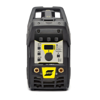
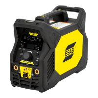
  • Control Panel: The front panel features a display, welding current control knob, options button, and process selection button. Indicators for overheating, VRD function, trigger mode, pulse mode, frequency, MMA, TIG Live, and TIG HF are present.
  • Process Selection: Users can select between TIG HF, TIG Live, and MMA welding modes.
  • Advanced Features (TIG HF or TIG Live mode): By pressing the process selection button for 3 seconds, users can access and adjust parameters such as:
    • Gas pre-flow time (PREG 0 - 5 s)
    • Start current (IGNA 10 - 100%)
    • Up slope time (SLPU 0 - 10 s)
    • Down slope time (SLPD 0 - 10 s)
    • End current (FINA 10 - 100%)
    • Gas post-flow time (POSG 0.5 - 15 s)
    • Background current (BKGA 10 - 100%)
  • Advanced Features (MMA mode):
    • Hot start (HOTS -10 - +10): Temporarily increases current at the beginning of the weld to reduce fusion issues and electrode sticking.
    • Arc force (ARCF -10 - +10): Adjusts current response to arc length variations, allowing for a calm arc with less spatter (low value) or a hot, digging arc (high value).
    • Cellulose electrode (CELL On / Off)
  • Options Button (common for all modes): Used to set:
    • Trigger mode (2 stroke / 4 stroke)
    • Pulse mode (On / Off)
    • Frequency (0.2 - 500 Hz) – only if Pulse mode is ON.
  • Fan Control: The "fan as needed" feature automatically switches the cooling fan off when not required, minimizing power consumption and reducing the intake of contaminants like dust.
  • Thermal Protection: The unit includes thermal protection against overheating. If overheating occurs, welding stops, an indicator lights up, and an error message appears on the display. The protection resets automatically once the temperature decreases.
  • Voltage Reduction Device (VRD): Ensures that the open-circuit voltage does not exceed 35 V when not welding. An indicator on the panel confirms VRD activation. This function can be activated by an authorized ESAB service technician.
  • Remote Control: The device supports remote control functionality. When a remote control is connected, it is automatically activated, and the maximum welding setting is determined by the front panel control.
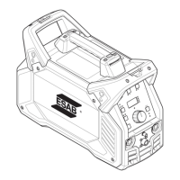
  • Portability: Equipped with a handle for easy carrying.

Maintenance Features

Regular maintenance is crucial for safe and reliable operation and to extend the lifetime of the power source.

  • Before Each Use:
    • Verify that the product and cables are not damaged.
    • Ensure the torch is clean and undamaged.
  • Routine Maintenance Schedule:
    • Every 3 months:
      • Clean or replace unreadable labels.
      • Clean weld terminals.
      • Check or replace weld cables.
    • Every 6 months:
      • Clean inside the equipment using dry compressed air with reduced pressure.
  • Cleaning Instructions:
    • Disconnect the power source from the mains supply before cleaning.
    • Open the enclosure and use a vacuum cleaner to remove accumulated dirt, metal filings, slag, and loose material.
    • Keep shunt and lead screw surfaces clean to prevent reduction in output welding current due to accumulated foreign material.
    • Always wear recommended personal safety equipment (ear plugs, safety glasses, masks, gloves, and safety shoes) during cleaning.
  • Coolant (if equipped with ESAB cooler): Use only ESAB approved coolant (ordering number: 0465 720 002) to prevent damage and maintain product safety.
  • Repair Work: Any repair or electrical work must be performed by an authorized ESAB service technician using only original ESAB spare and wear parts. Unauthorized repairs will invalidate the warranty.
  • End-of-Life Disposal: Electronic equipment must be disposed of at a recycling facility in accordance with European Directive 2012/19/EC and national laws. Users are responsible for obtaining information on approved collection stations.

ESAB ET 200iP Pro Specifications

General IconGeneral
BrandESAB
ModelET 200iP Pro
CategoryWelding System
LanguageEnglish

Related product manuals