9
1.4 TORCH ACCESSORY GUIDE & SELECTION -
Fig. 1.4, & Tables 1.4.1, 1.4.2 and 1.4.3.
Standard Duty Tips and Nozzles provide good perfor-
mance and service life for the majority of welding
applications.
Heavy Duty Tips, Tubes and Nozzles improve the per-
formance and extend the service life when used with
high current applications, high spatter wires, pulsed arc
mig and when used in confined areas.
Extra Heavy Duty (brass) Slide-on Nozzles provide
improved service life when subjected to extreme im-
pact abuse.
Extra Heavy Duty Threaded Nozzles and Heavy Duty
Tips and Tubes extend the rating of the MT-400 from
400 amps to 500 amps @ 60% duty cycle.
Accessory Selection - Assembly Guide .. see Fig. 1.4
Contact Tips and Tubes .................... see Table 1.4.1
Nozzles (slip-on or threaded) ............ see Table 1.4.2
Liners ............................................... see Table 1.4.3
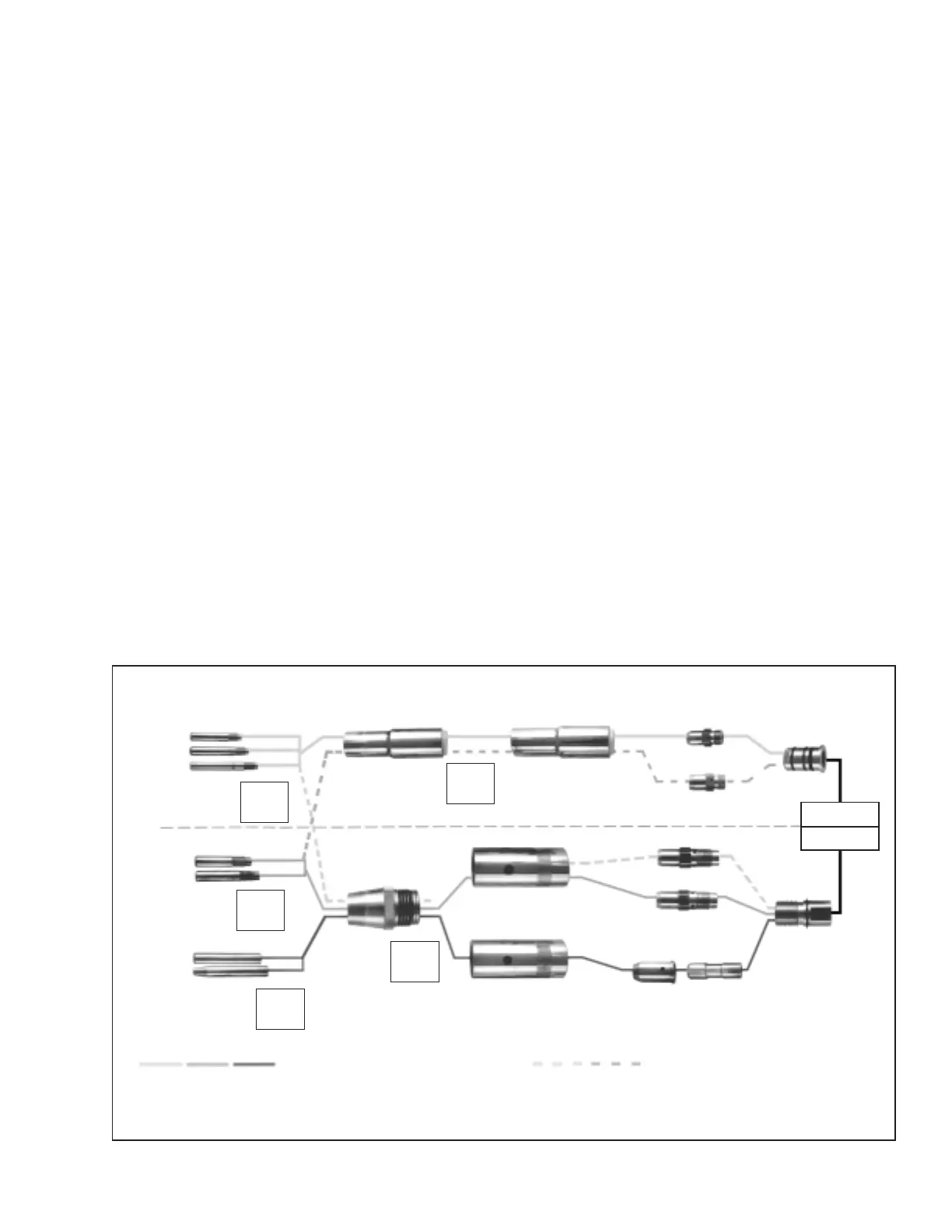
Figure 1.4 Accessories Selection - Assembly Guide
To select correct accessories, choose tip based on wire and follow Guide Chart to determine nozzle and adaptors.
CONTACT TIPS
AND TUBES
STANDARD DUTY CONTACT TIPS
ADAPTORS
NOZZLES
SLIDE ON SELF INSULATED NOZZLES
MT-200
MT-400
STANDARD DUTY
SEE TABLE
1.4.1
FOR PART
NUMBERS
.023" M or L .052" S or M
.030" M or L 1/16" S or M
.035" M or L 5/64" S or M
.045" - 3/64" S, M or L
SHORT (S)
MEDIUM (M)
LONG (L)
SEE TABLE
1.4.1
FOR PART
NUMBERS
#6 TAPERED #12
#8 #12 SPOT
#10
EXTRA HEAVY
DUTY
HEAVY DUTY
#8
#10
#12
#12 SPOT
#12 BRASS
STANDARD ACCESSORIES
SEE TABLE
1.4.2
FOR PART
NUMBERS
HEAVY DUTY CONTACT TIPS
EXTRA HEAVY DUTY
THREADED NOZZLES
SHORT (S)
MEDIUM (M)
.045" - 3/64" M 1/16" M
.052"M 5/64" M
3/32" M
SEE TABLE
1.4.1
FOR PART
NUMBERS
HEAVY DUTY CONTACT TUBES
SHORT (S)
MEDIUM (M)
.035" M 1/16" M
.045" - 3/64" M 5/64" S
.052" M 3/32" S
SEE TABLE
1.4.2
FOR PART
NUMBERS
#8
#10
#12
#16 SPOT
P/N 948785
P/N 17766 (.045" - 1/16")
P/N 948786 (5/64" - 3/32")
P/N 17135
P/N 17136
P/N 17154
P/N 17318
P/N 948793
COLLET BODY
COLLET
PRIMARY USE OF ACCESSORIES
ALTERNATE USE OF ACCESSORIES
ACCESSORIES FOR EXTENDED RATING
*
NOZZLE ADAPTOR
EXTRA HEAVY
DUTY
ADAPTOR
TIP ADAPTOR
TIP ADAPTOR
P/N 17983
P/N 17984
P/N 999452
NOZZLE
ADAPTOR
* Using Heavy Duty contact tips or tubes and Extra Duty threaded
nozzles will increase the rated capacity of the MT-400 to 500 amps.
II. INSTALLATION
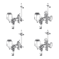
1. Install the proper feed roll (see Table 1.3) to the
wire feeder. Refer to the wire feeder booklet for
installation and adjustment details.
2. Connect the proper wire outlet guide (see Table
1.3) to the wire feeder connector assembly as
shown in figure 1.3.
3. Secure the outlet guide into the front clamp of the
accessory support assembly on the wire feeder
(refer to wire feeder instruction booklet).
4. Connect the power cable, gas hose, and switch
cord to the wire feeder (see Fig. 2.1)
5. Remove retaining pin on wire feeder connector;
insert torch inlet fitting fully; and then reinsert re-
taining pin to lock fitting in place. Be sure retaining
pin is completely pushed in before feeding the wire.
6. Use the inching switch on the wire feeder to inch
the wire through the torch.
7. The torch is now ready to operate. Refer to your
wire feeder instruction booklet for operating de-
tails.