62
SECTION 6 TROUBLESHOOTING
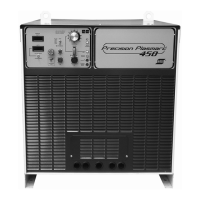
6.11 Low Current Range
TheEPP-450operatesineitherLOWorHIGHcurrentoutputranges.TheLOWrangeisusedformarkingfrom10to100
amperesandcuttingfrom35to100amperes.TheHIGHrangeisusedforcuttingfrom50to450amperes.
IntheHIGHrange,boththeleftandrightpowersourcesareused.Eachsidecontributes50%ofthetotaloutputcurrent.
Theleftsideactsasamasterpowersourcebysynchronizingtheswitchingoftherightsidetoitsownswitchingfrequency
of10KHz.
IntheLOWrange,onlytheleftpowersourceisused.Thenormallyopencontact,K13(6,9)preventsT7fromsupplyingbias
supplypowertoPCB-3,therightPWM/IGBTGateDrivePCBoard.Thisdisablestherightside.
ThesameK13contact(squarelabeled“D”ontheschematicdiagrams)placestheEPP-450intheHIGHcurrentmode.In
additiontoprovidingbiaspowertoPCB-3intheHIGHcurrentmode,this115VACisfedintoPCB-10P1-2.
PCB-10performstwofunctions.WithnoinputonPCB-10P1-2,PCB-10scalesthe0to10VDCcurrentreferencesignalfor0
to100amperes(LOWrange).IntheLOWrange,PCB-10P4-11/P4-12providesasignaltoPCB-2P4-1/P4-2.Thissignalcom-
mandsPCB-2,theleft(master)PWM/IGBTGateDrivePCBoardtochangetheswitchingfrequencyfrom10KHzto25KHz.
ThehigherswitchingfrequencyresultsinthemorepowerdissipationbytheheatsinksonPCB-3.Therefore,intheLOW
currentmode,asmallfan,M5,turnsontoprovideadditionalcooling.M5doesnotoperateintheHIGHcurrentmode.
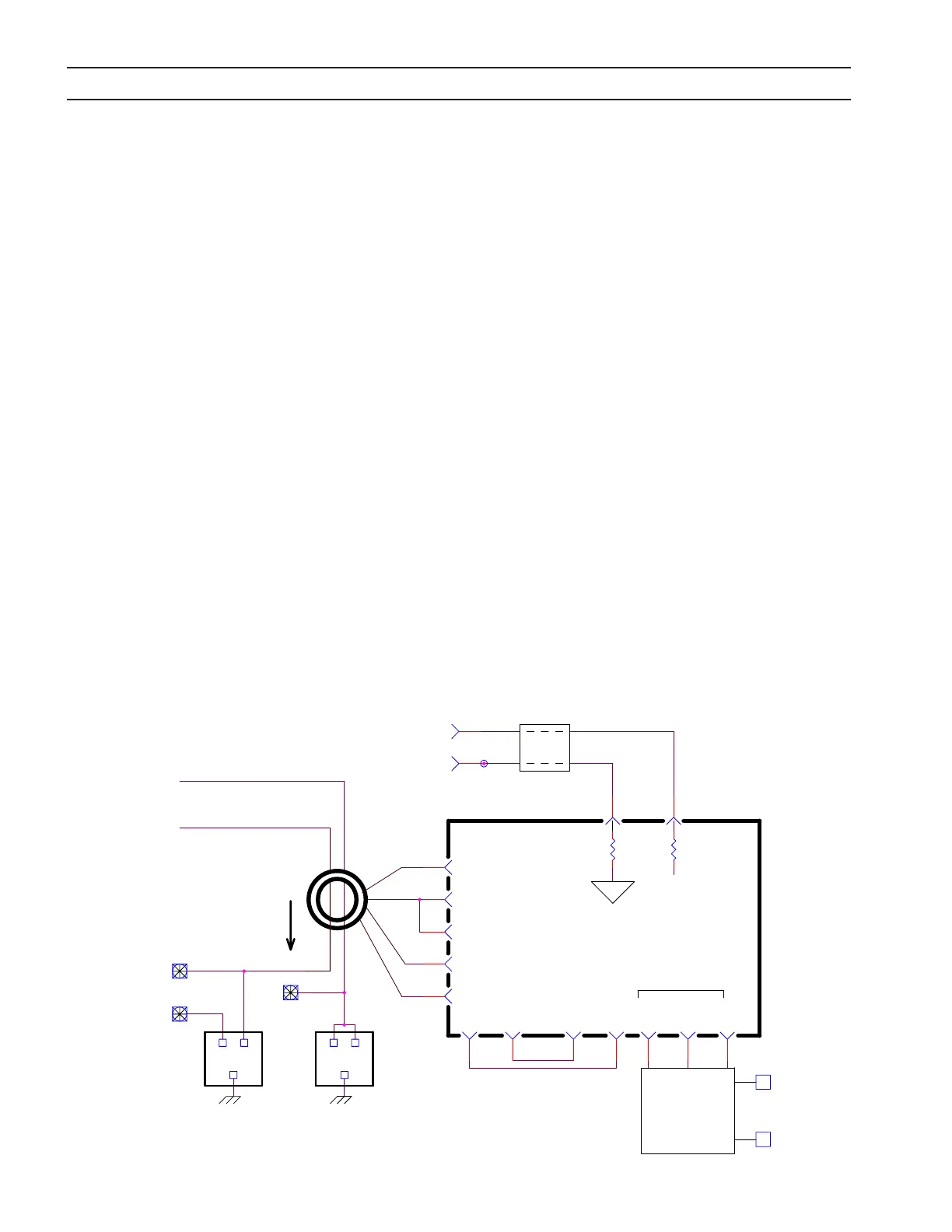
6.12 Electrode Current Transducer Circuit
-
J1-J
1V=100A
50
-
P4-7
+
+
TB1-5
J1-Y
P4-8
4
3
2
1
FN5
NOZZLE
SIGNAL -P4-1
HALL
ARROW
TD3
P1-1
P1-2
P1-3
P1-4
ELECTRODE
CURRENT
TRANSDUCER
P4-6
+15S
SIGNAL +
S COM
-15S
P4-4
P4-2
P4-5
FN2
12
3
50
S
P3-2
ANALOG
SCALING
BOARD
PCB11
P3-1P1-2 P1-1
FN1
12
3
J1-J & TB1-5, DC
SIGNAL COMMON
(NEG), ALSO
SHOWN ON PAGE 2
ELECTRODE
T11
SEC: 40VCT
PRI: 120V
20V 20V
H2
H1
P3-3
P3-4
P3-5
S BIAS
120V
H
N
TO PILOT ARC CONTACTOR, K4-T1
TO SHUNT NEG.
ELECTRODE CURRENT TRANSDUCER CIRCUIT
(TB10)
+
WORK
TheElectrodeCurrentTransducerCircuitprovidesagalvanicallyisolatedsignaltotheplasmacontrolindicatingthepower
sourceoutputcurrent.Thescalingofthesignalis:VOUT=IELECTRODE/100.Forexample,200Aresultsin2.0Voutput.The
scalingisthesameforbothhighandlowcurrentranges.Theoutputsignalresistanceis100Ohms.
PCB11receivesthesignalfromtheHallEectTransducerandsendsthesignalthroughFN5toJ1-Y(+)andJ1-J(-).PCB11sup-
plies+15Vand-15Vtooperatethetransducer.Italsobuersthesignaltopreventdamagetothetransducerfromvoltage
transientsgeneratedoutsidethepowersource.