7
2. Insert a torch liner (and support liner, if used) through
the mounting bracket on the rear of torch until it is
rmly seated within the torch.
3. Slip a torch inlet guide tip, of the proper size, over the
protruding end of the liner and screw it into the end
of the mounting bracket.
4. With the insulator sleeve (14N14) in place over the
mounting bracket (step 1-d), insert the bracket into
the clamp on the accessory support assembly of the
welding head. Secure the bracket by tightening the
locking handle on support assembly clamp. Connect
the service lines to plumbing box, connection block,
or directly to supply sources using service line exten-
sions and couplings where necessary.
Table 4 - Wire Feed Accessories for Remote Mounting
NOTE: See Tables 1 and 2 for nozzle and contact tube/tip requirements.
Wire Conduit* Wire Outlet Guide Outlet
Wire Size Torch Conduit Guide
type in. Liner 4-ft. 6-ft. 10-ft. Liner** EH-10A Insert
HARD .045 690514 38V86 39V99 40V18 None 39N15† None
.052 690514 38V86 39V99 40V18 None 39N15† None
1/16 690514 38V86 39V99 40V18 None 39N15† None
5/64 993844 38V89 40V01 — None 62N17†† None
3/32 993844 38V80 39V83 40V20 None 62N17†† None
CORED .045 690514 38V86 39V99 40V18 None 39N15† None
.052 690514 38V86 39V99 40V18 None 39N15† None
1/16 690514 38V86 39V99 40V18 None 39N15† None
5/64 993844 38V89 40V01 — None 62N17†† None
3/32 993844 39V80 39V83 40V20 None 62N17†† None
7/64 — 39V80 39V83 40V20 None 39N16 None
SOFT 3/64 993901 38V89 40V01 — 42V74 29N13 05N57
1/16 — 39V80 39V83 40V20 42V75 29N13 12N75
3/32 — 39V80 39V83 40N20 42V73 29N13 05N58
* Requires adaptor, P/N 61N59, in place of torch inlet guide tip (on torch mounting bracket).
** Conduit liners must be cut to the proper length to allow 1/16-in. clearance between liner and contact tube.
† Includes replaceable sleeve (995692).
†† Includes replaceable sleeve (995693)
III. INSTALLATION
Depending on the choice of mounting system used,
either direct or remote, install the wire feed components
as outlined below and illustrated in Figures 1 and 2.
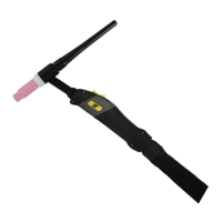
A. DIRECT MOUNTING TO EH-10A WELDING HEAD
(Refer to Figs. 1 and 3)
1. Install the torch mounting bracket (accessory part No.
633885) on the ST-21M as follows:
a. Loosen (and if necessary, remove) the setscrew
located in the recessed hole at the rear of the torch
barrel.
b. Place the small spacer tube (633887, supplied)
into the conduit connection tting at the rear of the
torch barrel, and tighten the setscrew to secure the
tube.
c. Slip the mounting bracket, large end rst, over
the rear torch barrel and the attached spacer and
then, using the 1/4-in. capscrew supplied, tighten
the bracket around the torch barrel.
d. Place the insulator sleeve (14N14, supplied) over
the end of the mounting bracket.