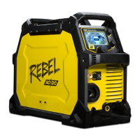
Do you have a question about the ESAB DTG 405 and is the answer not in the manual?
High-level circuit diagram illustrating the unit's main functional blocks.
Detailed wiring diagram showing all electrical connections between components.
Illustrates the functional relationships and signal flow between different modules.
Schematic representation of the unit's internal structure and modules.
Details on input/output connections and gas connections for welding.
Explains the path of electrical energy through the unit's components.
Describes how control and adjustment functions operate, including user interface elements.
Details safety circuits, including overvoltage and start-up signal paths.
Diagram showing the physical location of components on module A1.
Details on module A1's functions, including start-up, supply, monitoring, and protection.
Diagram showing the physical location of components on module A2.
Explanation of module A2's general functions and specific ramps.
Diagram showing component layout for modules A4 and A11.
Diagram showing component layout for modules A5 and A12.
Methods for testing modules A4, A5, A11, A12, including measurements and gate pulses.
Diagram showing the physical location of components on module A6.
Explanation of module A6's functions including supply, HF ignition, arc sense, and cooling.
Diagram showing the physical location of components on module A8.
Explanation of module A8's monitoring and control functions.
Component layout for modules A9 and A13.
Component layout for modules A10 and A14.
Component layout for the interference suppression filter A15.
Component layout for the sense transformer T2.
Guidelines for safe practices during repair and fault tracing.
Covers tests for protective conductors, insulation, and dielectric strength.
Discusses using power supplies, loads, and instruments for fault diagnosis.
Explains error codes displayed by the unit and their possible causes.
Procedures for using the IT01 tester to diagnose electronic modules.
General guidance and preparation steps before starting the unit.
Procedures for testing and commissioning the main power section.
Specific steps for commissioning the control module A2.
Basic safety, connections, remote control, and overheating protection.
Detailed explanation of all controls, potentiometers, and LEDs on the control panel.
Describes different welding modes (MMA, TIG) and parameter settings.
Routine checks and cleaning recommendations for the unit.
Details on available remote controls and other accessories.
| Input Frequency | 50/60 Hz |
|---|---|
| Efficiency | 85% |
| Input Voltage | 400 V |
| Welding Processes | MIG/MAG |
| Protection Class | IP23 |
