- 31 -
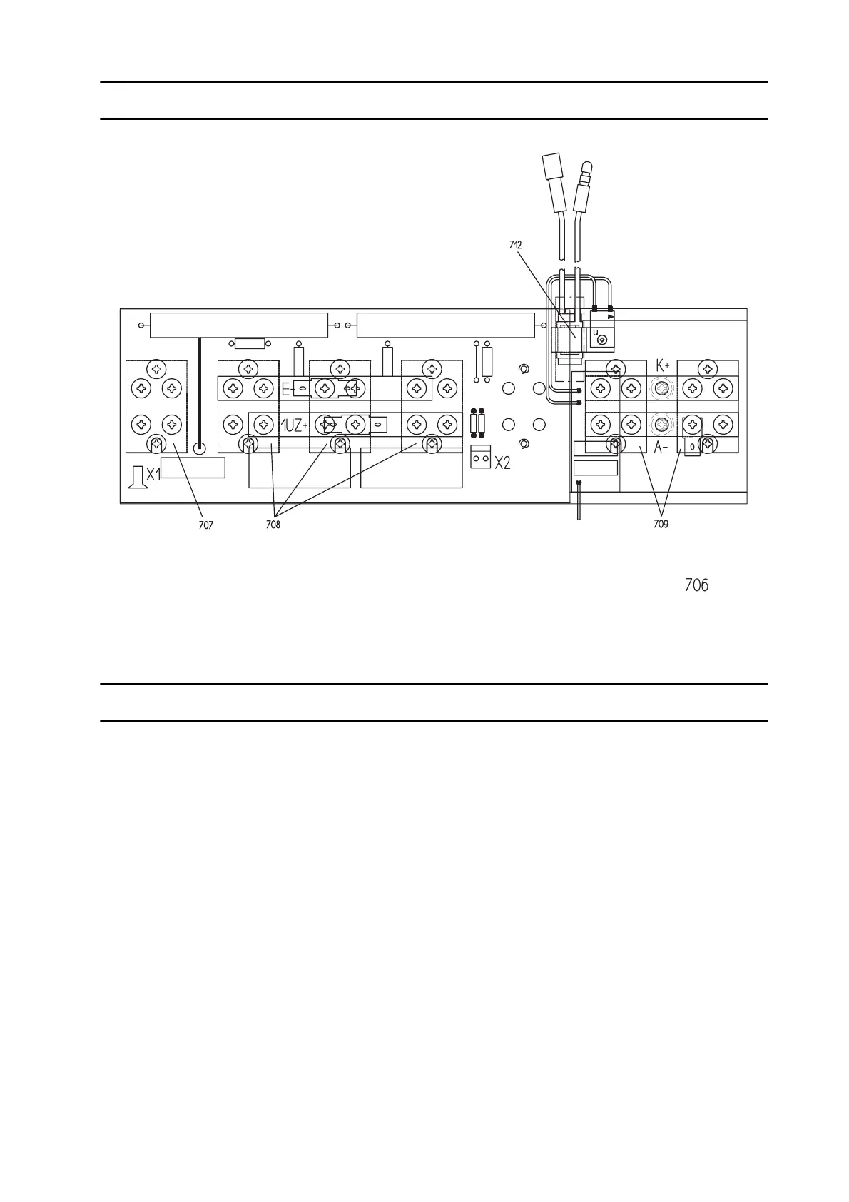
A5, A12 COMPONENT POSITIONS
Warning! The circuit and its parts are connected to mains voltage potential.
TESTING MODULES A4, A5, A11, A12
MEASUREMENTS ON AN ENCLOSED POWER BLOCK
CHECKING WITH TESTER IT01
Disconnect Molex control lead X11, X12 on A1 and connect to IT01. Switch position 1. Both gen-
erator LEDs must blink, or the particular MOSFET group defective.
CHECKING WITH MULTIMETER
Disconnect Molex control lead X11, X12 on A1. Use the multimeter to measure the ohmic resist-
ance between pins 1 and 2 of X11 (and X12). If the MOSFETs are OK, the reading should be ap-
prox. 500 Ω
. Lower figures indicate a defective MOSFET group.
MEASUREMENTS ON AN OPEN POWER BLOCK
CHECKING THE MOSFETS AND DIODES
Use a multimeter to measure in the diode test mode. Test in the reverse and the forward directions
of the diodes and MOSFETs. IMPORTANT REMINDER: Measurements must be made on cold
modules. On hot modules, the measurement can be affected by residual current.