- 37 -
A8 ensures the following limits:
• No-load voltage
• Minimum DC output current (TR3)
• Minimum AC output current (TR6)
• Maximum output current (TR4)
• Limits of AC and DC output voltage
• Minimum inverter frequency (TR1)
• Maximum inverter frequency (TR2)
• Maximum short-circuit time of the load circuit before current reduction
(can be switched off by J1);
A8 generates the following control signals:
• Pulse-width-modulated (PWM) inverter clock control signals for A1
• Control signals for A9, A13 and A10, A14 (A8-3)
• Status feedback signals to A2
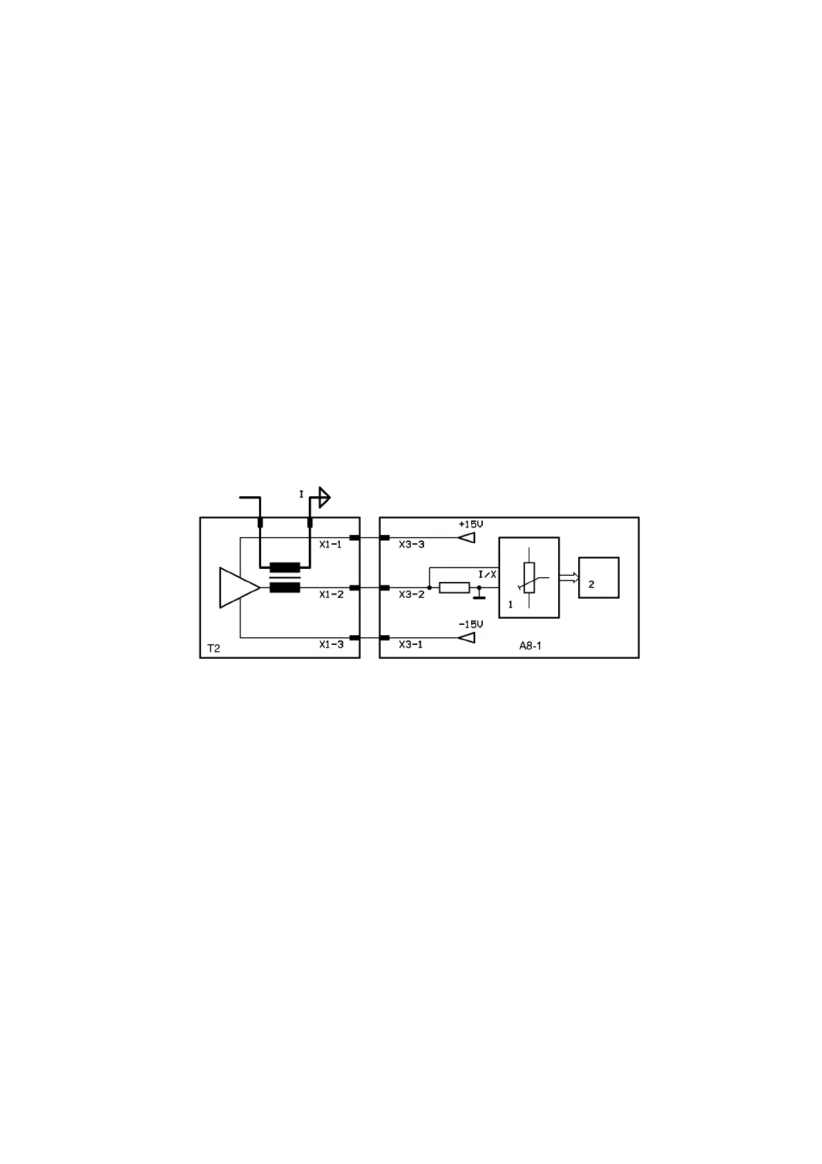
A8-1 SECONDARY CURRENT MONITORING
T2 is a floating DC current transformer. The current signal I/X images 1/2000th of the weld current.
In 1, the level for the maximum output current is set to 5 V by TR4 and transferred to the following
stages 2.
NOTE! The signal I/X at X3-2 is only intended for internal use to control the unit. This signal must
not be tapped for other purposes, e.g. for additional displays or current evaluation. In the worst
case, tapping this signal could destroy the AC converter!
a8-1.pcx