- 12 -
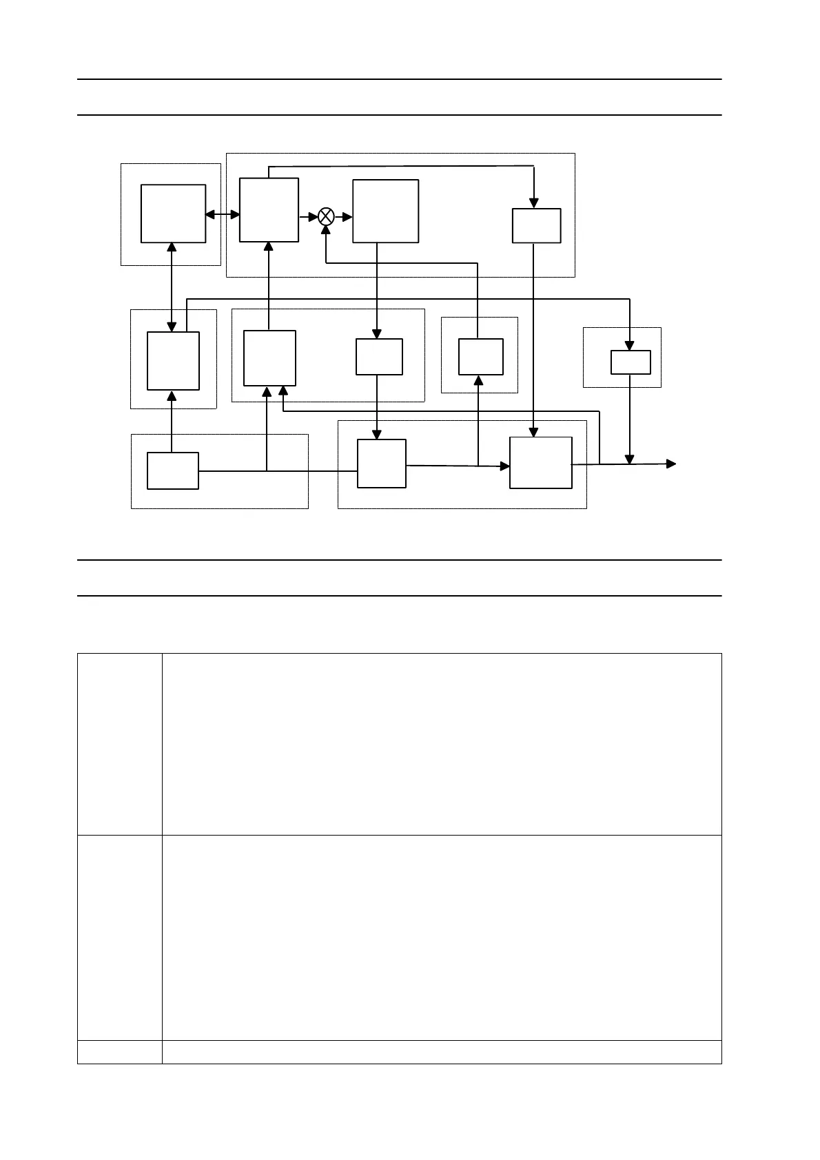
FUNCTION DIAGRAM DTG 405
COMPONENT DESCRIPTION
This component description refers to the block diagram on the following pages.
A1 Designed to ensure the basic primary inverter control, monitoring and protective
functions. It comprises:
• start-up circuit
• primary switch mode power supply for internal supply
• power supply for A8
• potential separation, primary MOSFET-drivers for A5, A12,
• security logic and control for primary inverter
• thermal switch monitoring
A2 Designed to ensure and manage the advanced operating parameters and mode
control. It comprises:
• (A2-1) input for remote control
• (A2-1) sequencer control
• (A2-1) current value and current slope control
• (A2-1) solenoid valve control
• (A2-1) HF ignition control
• (A2-2) front panel analogue and digital settings
• (A2-2) front panel displays
A3 Mains rectifier 75A/1200V
welding
process
control
pulse
with
modulator
driver
display
control
interface
control,
supply
parameter
inverter
supply
control,
driver
current
sense
hf-unit
primary
power
secondary
power
stage
stage
mains
supply
welding
circuit
Power block
A2
A8
A6
A1
T2
A7
A3, A15, C1..C4
T4
A4, A5, A9, A10, A11, A12, A13, A14