- 35 -
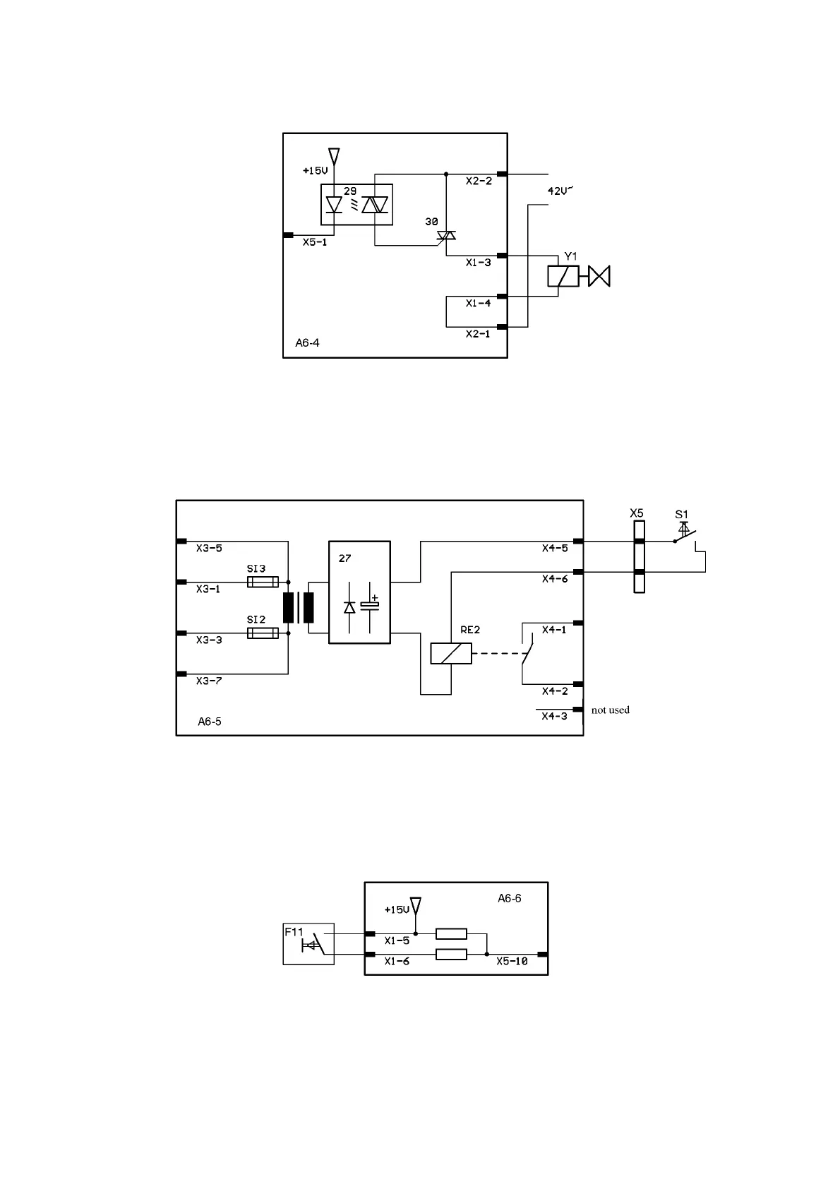
A6-4 SOLENOID VALVE CONTROL
The gas valve is controlled from A2 via X5-1. Easy test of the gas valve: Make short circuit be-
tween X2-2 and X1-3.
A6-5 TORCH BUTTON MONITORING
The Torch button signal S1 is potential-isolated by RE2 and is transferred via X4-1,2 to A2. The
supply voltage to X3 is 230 V; a transformer and 27 are used to provide a potential-isolated aux-
iliary voltage supply to RE2.
A6-6 MONITORING THE COOLING CIRCUIT
A pressure switch F11 monitors the pressure in the cooling circuit. When pressure is applied, the
pressure switch is closed. A pressure drop resulting from a defective cooling unit is reported to A2
via X5-10 by means of an L signal. A2 then displays Error Code 5.
a6-4.pcx
a6-5.pcx
a6-6.pcx