- 22 -
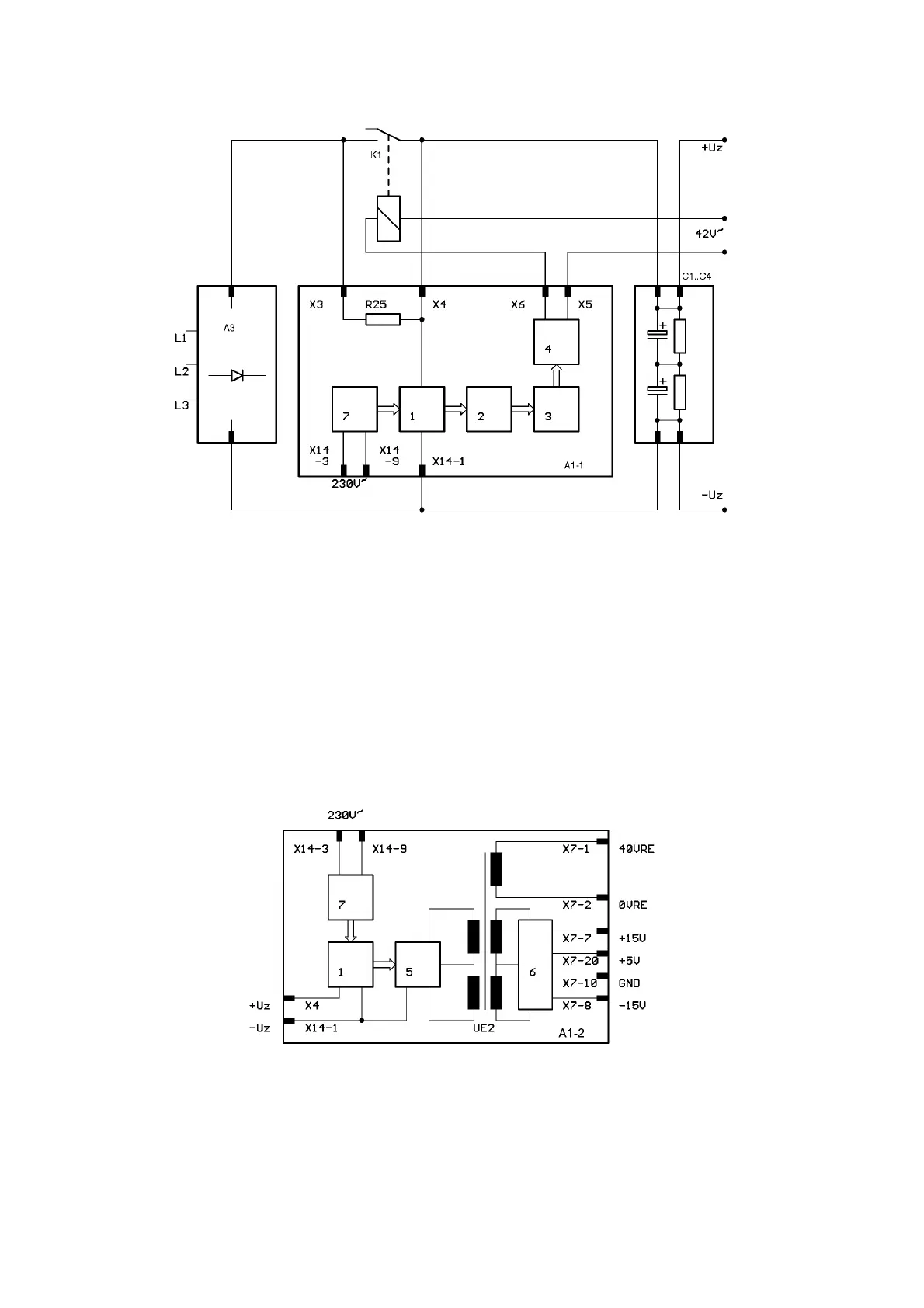
A1-1 START-UP CIRCUIT
Warning! The circuit and its parts are connected to mains voltage potential.
The voltage supplied by rectifier A3 charges the link buffer capacitors C1 to C4 to link voltage (UZ)
via the charging resistor R25. A start-up circuit 7 initially powers the primary supply 1. Then, start-
ing at a link voltage of about 40 V, the primary supply begins to work on its own. Once all the in-
ternal supply voltages have reached their setpoints, the comparator circuit 2 provides the start-up
signal for a timing stage 3. After time-out of a delay of about 1 second, the main contactor K1 is
closed via a switching stage 4. At the same time, the drive circuits for the inverter are enabled (see
section A1-5 and section A1-7).
A1-2 SUPPLY INVERTER
Warning! The circuit and its parts are connected to mains voltage potential.
The start-up supply 7 is powered with 230 V AC. It starts the primary supply 1. The primary supply
1 generates a stabilised voltage of approx. 40 V. Inverter 5 in conjunction with transformer UE2
generate a potential-isolated square-wave AC voltage of 40 V amplitude acting as a potential-iso-
lated supply for the MOSFET driver circuits on A1 and A8. A rectifier and stabiliser 6 generate
potential-isolated voltages of +15 V, 5 V, and -15V for A1 and A8.
a1-1.pcx
a1-2.pcx