- 23 -
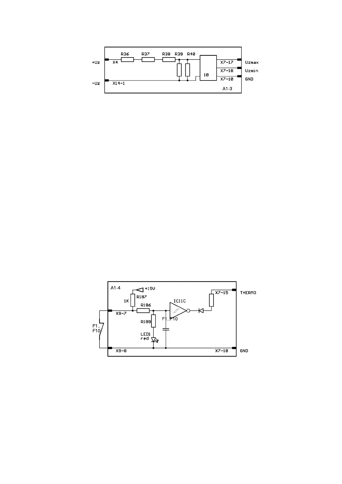
A1-3 MAINS VOLTAGE MONITORING
Warning! The circuit and its parts are connected to mains voltage potential.
The voltage divider comprising R36 to R40 divides the link voltage UZ at a ratio of about 200:1.
This voltage is evaluated by a comparator circuit 10. When the maximum allowed link voltage of
660 V DC (equivalent to a mains voltage of approx. 460 V AC) is exceeded, the signal on X7-17
is L-activated (UZmax). When the link voltage drops below the minimum of 420 V DC (equivalent
to a mains voltage of approx. 300 V AC), the signal on X7-18 is L-activated (UZmin). Signals from
the mains voltage potential to the potential of the control are transferred in 10 via an opto-coupler.
• Response of the unit in the event of mains overvoltage: Inverter is tripped; Error Code 3 on
front panel.
• Response of the unit in the event of mains undervoltage: Inverter is tripped; Error Code 2 on
front panel.
NOTE!
If a minor mains undervoltage occurs, the power of the unit may decrease even if Error
Code 2 is not displayed.
NOTE! If an excessive mains voltage > 500 V AC occurs starting with a link voltage UZ of about
730 V DC, the supply of A1 and A8 attempts to protect itself by performing a complete shut-down.
In this case, the front display shows Error Code 5, provided the supply on A6 is not defective.
A1-4 TEMPERATURE MONITORING
A 'chain' of thermal switches F1 to F10 is provided to monitor the temperature of key components
in the system. A current of approx. 15 mA flows through the chain of thermal switches. When the
temperature of a thermal switch exceeds the monitored temperature, the chain of thermal switch-
es is interrupted. In this case LED1 on A1 comes on. The signal to X7-15 is L-activated.
A8 then interrupts the weld current and Error Code 4 is displayed on the front panel. Once the
thermal switch has sufficiently cooled down, the thermal switch chain closes again. The error mes-
sage is reset and welding can be resumed.
The thermal switches have different temperature limits:
• F9, F10: power transformer T3, smoothing reactor L1: 130 °C
• F5, F6, F7, F8: heat sink A5, A12, A4, A11: 90 °C
• F1, F2, F3, F4: heat sink A9, A13, A10, A14: 80 °C
A1-3.pcx
a1-4.pcx