- 32 -
Figure: Locations of connections on MOSFET and diodes.
CHECKING THE GATE PULSES
CHECKING WITH TESTER IT01
Turn off the machine.
Disconnect the cables used to transfer driver signals to modules A5, A12 and A4, A11.
Using the auxiliary cable, connect the IT01 in succession to X11 and X12 of module A1.
Turn on the machine. Select the TIG 2 Cycle Lift-Arc mode, and press the Torch button.
If the gate pulses are OK, both the red and the green LEDs come on.
Cf. Procedure of "TEST PROCEDURE WITH IT01".
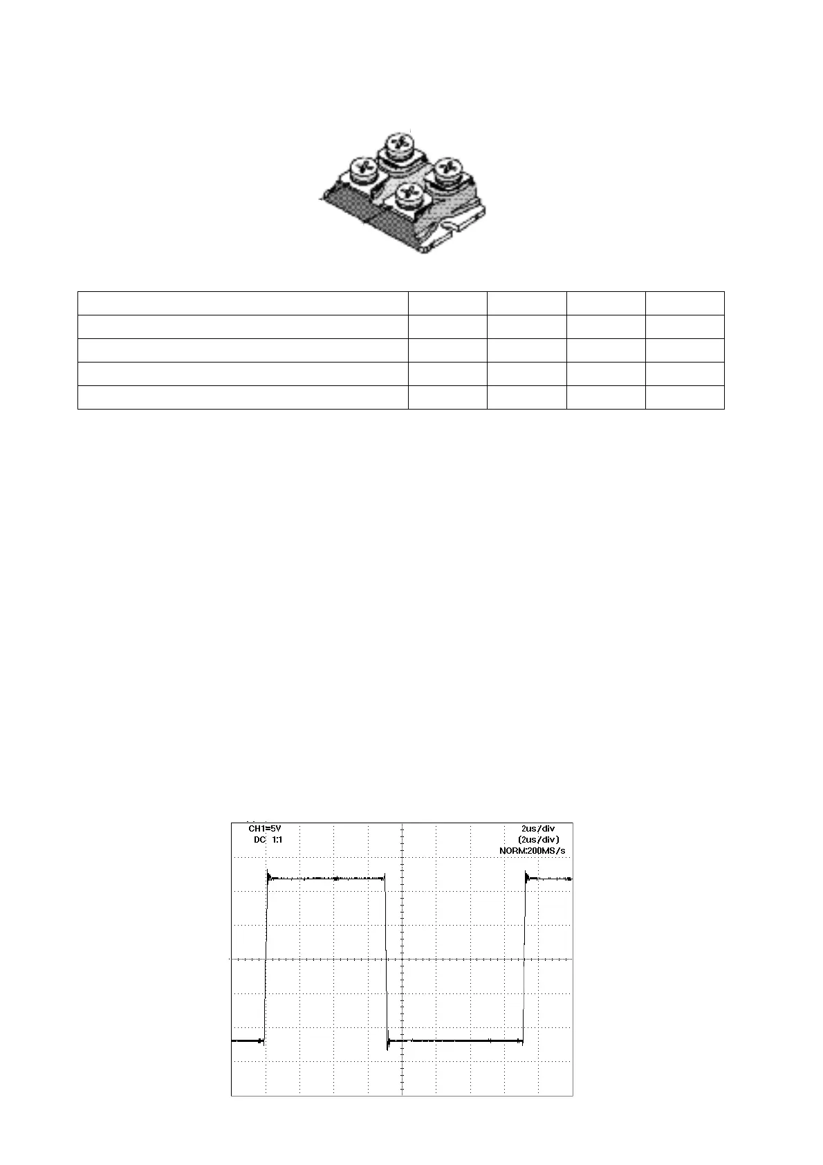
CHECKING WITH OSCILLOSCOPE
Turn off the machine.
Disconnect the cables used to transfer driver signals to modules A5, A12 and A4, A11.
Connect the GND of the oscilloscope to X11-1 (and X12-1) of module A1. Connect the sample
probe to X11-2 (and X12-2).
Turn on the machine. Select the TIG 2 Cycle Lift-Arc mode, and press the Torch button. The figure
below shows the correct waveform of the gate pulses at no load.
Pin assignment Pin 1 Pin 2 Pin 3 Pin 4
Mosfetmodul N-200V 100A Source Gate Drain Source
Mosfetmodul N-900V 26A Source Gate Drain Source
Rectifiermodul B200 P400 K1 A1 A2 K2
Rectifiermodul B23 P10 K2 A1 K1 A2
1
2
4
3