- 36 -
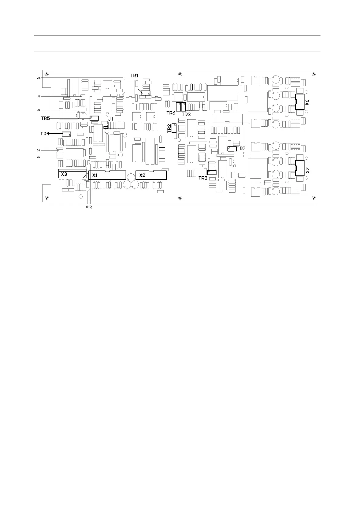
A8 COMPONENT POSITIONS
A8 DESCRIPTION OF OPERATION
A8 PRINCIPAL FUNCTION
The functions of A8 are very complex. An arrangement of analogue and digital circuits that char-
acterise the control function of certain welding modes is included on the board. All functions are
controlled by a PLD (programmable logic device) on the board.
The power supply to A8 comes from A1 (See section A1-2).
Front panel A2 provides the following default values for A8:
• Output current
• AC current frequency
• AC current balance
• Type of AC current curve
• DC or AC mode
• DC polarity
• Start/Stop signals
A8 determines the actual output current (A8-1), actual output voltage (A8-2) and all status mes-
sages of A1.
a8b.pcx