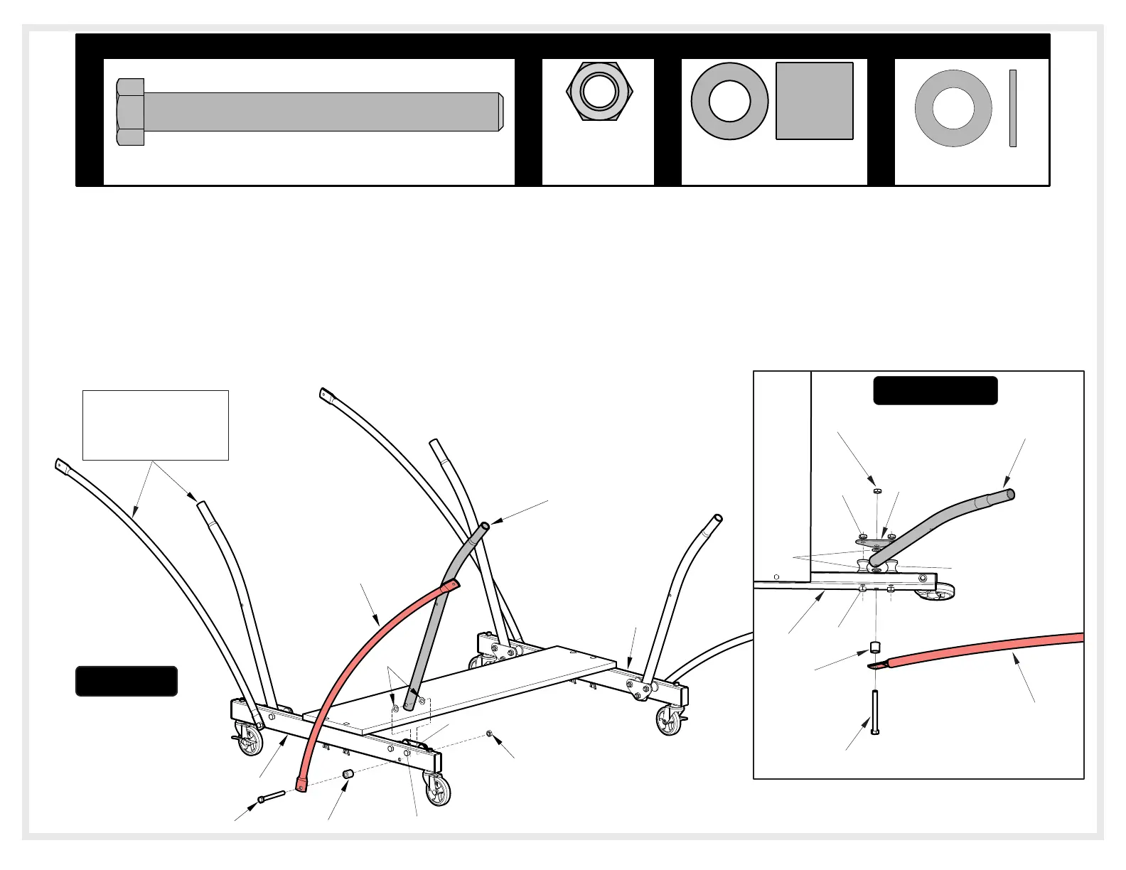
2. Attach Strut Tubes (#17) and Linkages (#16) to Caster Beam Assemblies (#8) as shown in Figure 2.
a) If necessary loosen Bolts (#13) and Nuts (#28) so that Strut Tube (#17) can fit between Support Plate (#43) and Caster
Beam (#8) as shown in the Top View and Figure 2.
b) Slide one Hex Bolt (#27) through one linkage (#16) one Spacer (#36) pass through Caster Beam (#8), followed by one
Plastic Washer (#39), Strut Tube (#17), another Plastic Washer (#39), inner Support Plate (#43) and Lock Nut (#28).
c) Repeat on other end of Caster Beam (#8) and on second Caster Beam.
d) Tighten Nuts (#28) on Bolts (#13) securely.
e) Tighten Nuts (#28) on Bolts (#27) securely.
17
8
39
16
13
8
43
Note: Linkages & Strut
tubes must be turned as
shown or table will not
operate correctly.
36
27
28
17
16
43
39
12
36
8
28
13
(Inner Plate)
27
28
TOP VIEW
3/8-16
Locknut
(Qty. 4)
28
HARDWARE NEEDED
27
3/8-16 x 3 1/2 Hex Head Bolt
(Qty. 4)
36 39
3/4" Long Spacer
(Qty. 4)
3/8" Plastic
Washer (Qty. 8)
Note: Dimples on Strut
Tubes are part of the
manufacturing process and
do not affect assembly.
2
Figure
5



 To Next Page