Z.
3.4.2
THINGS
TO
WATCH OUT FOR (cont.
i)
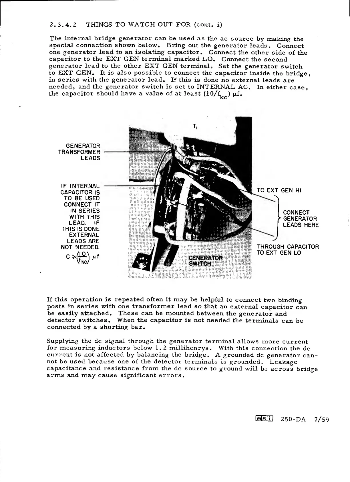
The internal bridge
generator
can be used
as
the ac
source
by
making
the
special connection
shown
below. Bring
out
the
generator
leads.
Connect
one
generator lead
to
an isolating
capacitor.
Connect the
other
side
of
the
capacitor to
the
EXT GEN terminal
marked
L.O.
Connect
the
second
generator lead
to
the other EXT
GEN
terminal.
Set the
generator
switch
to
EXT GEN,
It
is
also possible
to connect the
capacitor
inside
the bridge,
in
series
with
the generator lead.
If
this is
done
no
external
leads
are
needed, and the generator switch is set
to
INTERNAL
AC.
In either
case,
the capacitor
should have a value of
at least
GENERATOR
TRANSFORMER
LEADS
IF
INTERNAL
CAPACITOR
IS
TO
BE
USED
CONNECT
IT
IN
SERIES
WITH THIS
LEAD.
IF
THIS
IS DONE
EXTERNAL
LEADS ARE
NOT
NEEDED.
"
"(ffc)
TO
EXT GEN HI
CONNECT
^
GENERATOR
LEADS
HERE
THROUGH
CAPACITOR
TO EXT
GEN LO
If
this operation is
repeated often
it may be
helpful
to
connect
two
binding
posts in series with
one
transformer
lead
so
that
an
external
capacitor
can
be
easily attached.
These can be
mounted
between
the
generator
and
detector switches. When
the
capacitor is not
needed
the
terminals
can
be
connected by a shorting bar.
Supplying the dc signal through the generator
terminal
allows
more
current
for
measuring inductors below 1.2
millihenrys.
With this
connection
the
dc
current
is not affected by balancing the
bridge.
A
grounded dc
generator
can-
not be used
because
one of the detector
terminals
is
grounded.
Leakage
capacitance
and resistance
from
the dc source
to
ground will
be across
bridge
arms
and may cause significant errors.
LeisI I
{
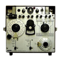
250-DA
7/59
 Loading...