Do you have a question about the ESI 250-DA and is the answer not in the manual?
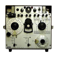
Selects the bridge circuit for inductance, resistance, or capacitance measurements.
The DEKASTAT decade resistor dial for reading measured resistance, inductance, or capacitance.
Terminals for connecting an external generator to the bridge.
Chooses the detector (galvanometer, external AC, or internal DC).
Selects the internal AC, internal DC, or external generator for the bridge.
Controls power and AC detector sensitivity; pilot light indicates power status.
Electron-ray-tube visual null indicator for high sensitivity and rapid response.
Fuse receptacle located in upper right-hand corner recess for bridge protection.
Red lamp on the left-hand side of the small upper panel indicates power supply.
Measures resistance, inductance, capacitance, dissipation factor (D), and storage factor (Q).
Step-by-step guide for connecting and measuring unknown resistors using the bridge.
Steps for adjusting for null, range selection, and final resistance calculation.
Covers high and low resistance measurement precautions and corrections.
Guide for measuring AC resistance, including phase correction and accuracy notes.
Details on setting controls, phase shift compensation, and accuracy for AC resistance.
Step-by-step guide for connecting and measuring unknown inductors using the bridge.
Explains the equivalent circuit for series and parallel inductances and their calculation.
Covers low and high inductance measurement precautions and effects.
Guidance on using DC for measuring iron core inductors sensitive to current variations.
Special connections and capacitor requirements for using the internal generator as AC source.
Recommendations for insulated batteries and power limiting resistor circuits.
Diagram and current limits for parallel inductance measurements with superimposed DC.
Defines power limiting resistor (R), isolating inductor (L), and capacitor (C).
Diagram and current limits for parallel inductance measurements with DC via detector terminals.
Defines key components R, L, C, Rd, MA for DC parallel inductance measurements.
Procedure to measure AC voltage applied to an unknown inductor using a voltmeter.
Procedure to measure AC current through an inductor using a voltmeter and conversion table.
Formula I = V x M for calculating AC current and table of multipliers.
Explains the sliding balance phenomenon and provides a technique to achieve null.
Guidance on using external rheostats to extend measurement ranges for D and Q.
Completes the parallel inductance circuit using an external rheostat for extended ranges.
Readings and calculation of Q for parallel inductance using an external rheostat.
Completes the series inductance circuit using an external rheostat for extended ranges.
Step-by-step guide for connecting and measuring unknown capacitors using the bridge.
Adjusting for null, calculating capacitance (C) and dissipation factor (D).
Explains equivalent circuits for series and parallel capacitance and their calculation.
Covers low and high capacitance measurement precautions and effects.
Guidance on using DC for capacitors needing polarizing voltage or to avoid reverse polarity damage.
Special connections and capacitor requirements for using the internal generator as AC source.
Recommendations for insulated batteries and power limiting resistor circuits for DC capacitance.
Diagram and circuit protection for parallel capacitance with superimposed DC via generator.
Procedure for adjusting DC voltage and measuring capacitance.
Procedure to measure AC voltage applied to an unknown capacitor using a voltmeter.
Explains sliding balance and provides a technique to achieve null for capacitance measurements.
Guidance on using external rheostats to extend measurement ranges for D and Q.
Completes the series capacitance circuit using an external rheostat for extended ranges.
Completes the parallel capacitance circuit using an external rheostat for extended ranges.
Instructions for connecting standard resistors as bridge elements for calibration or use.
Instructions for connecting the DEKASTAT variable resistor for measurements.
Instructions for connecting the standard capacitor as a bridge element.
Schematic diagram for the series inductance measurement configuration.
Schematic diagram for the parallel inductance measurement configuration.
Schematic diagram for the resistance measurement configuration.
Schematic diagram for the series capacitance measurement configuration.
Overview of fundamental bridge circuits for L, R, and C measurements, plus block diagram.
Comprehensive schematic of the entire impedance bridge circuit, showing component interconnections.
List of resistors, capacitors, switches, and meter with their part numbers and specifications.
Schematic of the generator and detector circuitry, including tubes and networks.
Component breakdown for resistors, capacitors, transformers, switches, tubes, and fuses.
Diagram showing the internal wiring connections of the bridge controls and components.
Illustrates the physical location of major components within the bridge chassis.
Illustrates the physical location of components in the generator-detector assembly.
Basic checks on controls, connections, and component status before troubleshooting.
Steps for systematic checking and troubleshooting without removing the chassis.
List of essential test equipment and tools required for servicing and calibration.
Table detailing symptoms, probable causes, and procedures for diagnosing bridge malfunctions.
Diagnosing issues with DC measurements, AC resistance, inductance, and capacitance.
Diagnosing inaccurate readings, power indicator failures, and switch/cable issues.
Diagnosing power fuse blowouts, filament failures, and DC supply issues.
Diagnosing issues with the visual null indicator and signal amplification.
Diagnosing oscillation failures, output signal issues, and frequency deviations.
Steps to set controls and measure DC generator voltage for proper operation.
Steps to set controls and check galvanometer deflection for proper functionality.
Table showing approximate galvanometer deflection for different detector switch settings.
Steps to set controls and check AC generator output waveform and amplitude.
Steps to set controls and check AC null indicator opening for detector functionality.
Steps to set controls and measure resistance values of the range resistors.
Table showing expected ohmmeter readings for range resistors based on multiplier switch settings.
Steps to set controls and measure resistance values of standard resistors.
Procedure to check the Main Dial DEKASTAT® resistance against its setting.
Procedure to check the D-Q rheostats, starting with R25.
Procedure to check R24 and R21 by setting controls and observing D-Q dial readings.
Procedure to check the standard capacitor's value against known specifications.
Instructions for safely removing the bridge chassis for inspection or repair.
Detailed steps for preparing and physically removing the bridge chassis.
Instructions for cleaning the case and reinstalling the bridge chassis.
Guidelines for mechanical adjustments and component replacement during repair.
| Type | Audio Interface |
|---|---|
| Channels | 2 |
| Phantom Power | Yes |
| Bit Depth | 24-bit |
| Analog Outputs | 2 |
| Connectivity | USB |
| Power Supply | USB bus-powered |