6 P-300 Web Controller Configuration and Troubleshooting Manual
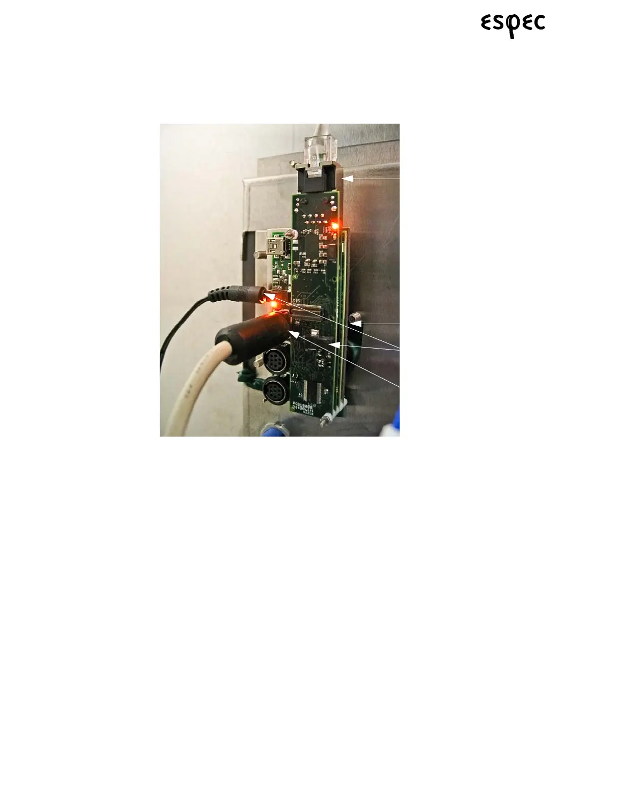
1.7 Hardware Connection & Installation Details
1. Power supply connection (2 power plugs to choose from)
2. Ethernet connection (to the Ethernet connector mounted in the option panel)
3. P-300 Web Control RS-232 Serial Cable connection to P-300 main board.
4. Micro SD card installation slot, in gumstix board
1.7.1 Hardware Installation Procedure
Use the following steps for a web server option installation:
1. Turn all power off to chamber before starting.
2. Mount the web server assemly onto the I/O Boards, using stand offs.
3. Connect the P-300/Web Control RS-232 communications cable between the P-300 main board connec-
tor CNM22 and the serial connection on the web server (labeled #3 on the image above).
4. Connect the Ethernet cable between the web server Ethernet connection (labeled #2 on the image
above) and the Ethernet port that goes to the outside of the chamber.
5. Install the web server firmware micro SD card, if it is not already installed. It slides into a small slot on
the “middle” gumstix board (labeled #4 on the image above).
6. Connect the gumstix power supply to the receptacle on the chamber electrical panel and plug the power
connector into one of the gumstix power supply connection plugs (labeled #1 on the image above).
7. Turn power back on to the chamber.