Copyright 2003-2013 CSM CO.,LTD
- 9 -
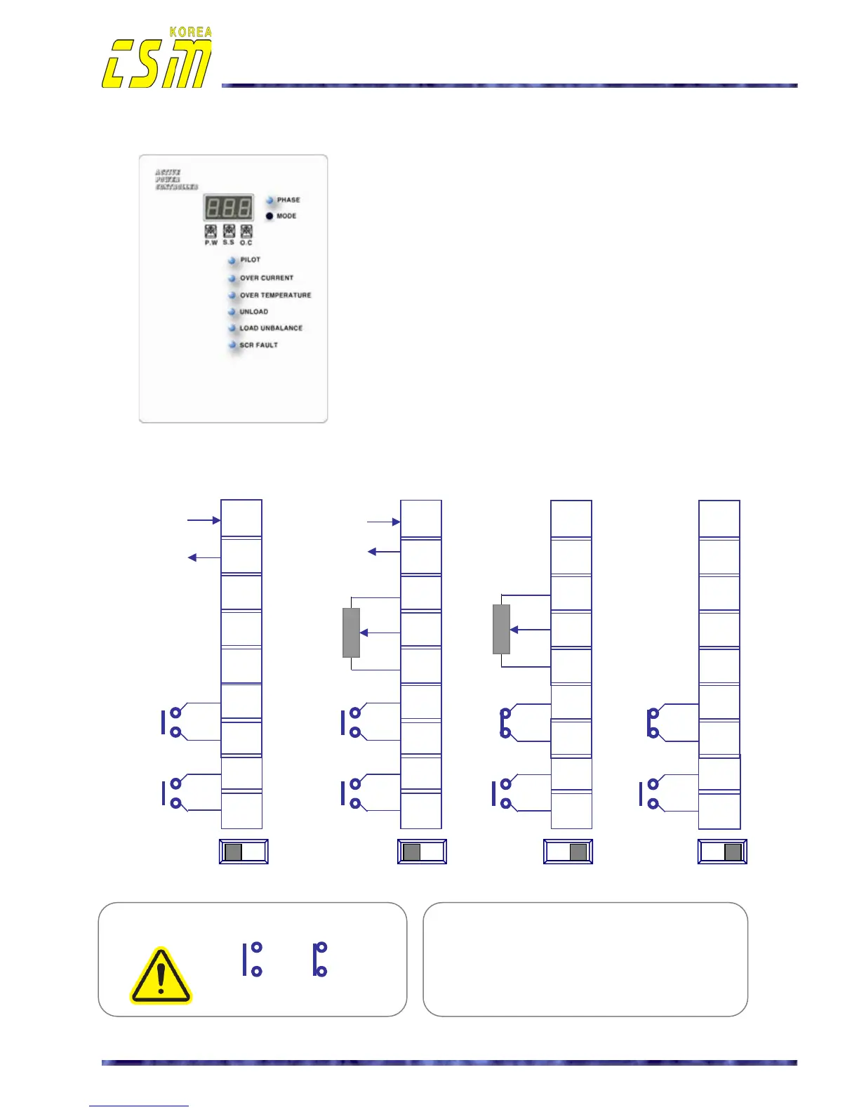
- R, S, T :
Main power input terminal labels.
- U, V, W :
Load (heater) connection terminal labels.
- 4-20mA (+)(-) : Analogue input line
- Potentiometer for manual set-point : 10KΩ, External
- RUN / STOP : External contact, RUN or STOP
- AUTO/MANUAL : External contact, Automatic or Manual
operation
APC-TF Series
External form and wiring diagrams
•
Automatic control
①
②
③
④
⑤
•
Automatic with
remote control by
external potentio meter
• Manual operation
• ON/OFF control
•
Product External form and description of the symbols
4-20mA (+)
4-20mA (-)
* The method of the RUN / STOP contact.
STOP
RUN
①
②
③
④
⑤
4-20mA (+)
4-20mA (-)
10KΩ
External -
potentio-meter
①
②
③
④
⑤
①
②
③
④
⑤
AUTO MANUAL
Operation mode
Switch (PCB)
*
Signal, control cables : Use the shield cable
(CVVSB: more then 0.75mm
2
)
* CVVSB : PVC INSULATED, COPPER WIRE
BRAID SHIELD AND PVC SHEATHED
CONTROL CABLE
•
Manual with
remote control by
external potentio meter
External
potentio meter
10KΩ
AUTO MANUAL
AUTO MANUAL AUTO MANUAL
⑥
⑦
AUTO/MAN
⑥
⑦
⑥
⑦
RUN/STOP
⑧
⑨
RUN/STOP
⑥
⑦
AUTO/MAN
⑧
⑨
RUN/STOP
⑧
⑨
⑧
⑨
AUTO/MAN
RUN/STOP
AUTO/MAN

 Loading...