2 / 8 P/N 3101773-EN • REV 04 • ISS 05AUG13
• When connecting the network data riser, always wire
the Network B (isolated) terminals on one SFS1-CPU
module to the Network A (nonisolated) terminals on
the next. See Figure 5.
• SLC wiring notes:
• SLC wiring is supervised.
• SLC2 (TB2) wiring is configured the same as SLC1
(TB1).
• When connecting SLC wiring, if shielding is used it
must be continuous, terminated at the shield terminal,
taped throughout the entire circuit, and free from earth
ground.
• SLC AUX power wiring is unsupervised.
• SLC AUX power on loops 1 and 2 is nonisolated and
not used for loop smoke power.
• SLC AUX power on loop 2 (TB2) is available whether
or not a second 3-SDC1 card is installed.
• SLC smoke power (SMK PWR) on loop 2 (TB2) is not
available unless a second 3-SDC1 card is installed.
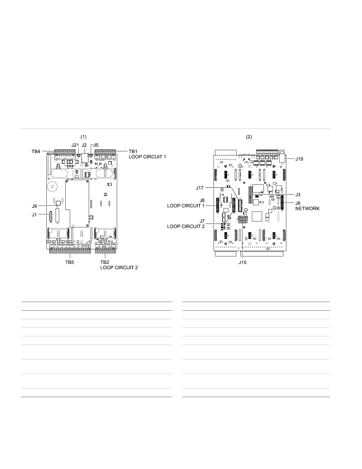
Figure 1: SFS1-CPU terminals and connectors
(1) SFS1-CPU front view
(2) SFS1-CPU back view
Table 1: SFS1-CPU terminals and connectors
Description
Description
Not used
Power supply cable connector
RJ-45 Ethernet cable connector
Data ribbon cable connector
Ethernet adapter card connector
RJ-11 telephone jack
Not used
Not used
RS-485 network and fiber network
option card connector
Loop 1 signaling line circuit wiring
terminal
Data circuit card connector for
signaling line circuit 2
Loop 2 signaling line circuit wiring
terminal
Data circuit card connector for
signaling line circuit 1
Common relay wiring terminal
LCD user interface connector
Network wiring terminal