P/N 3101773-EN • REV 04 • ISS 05AUG13 5 / 8
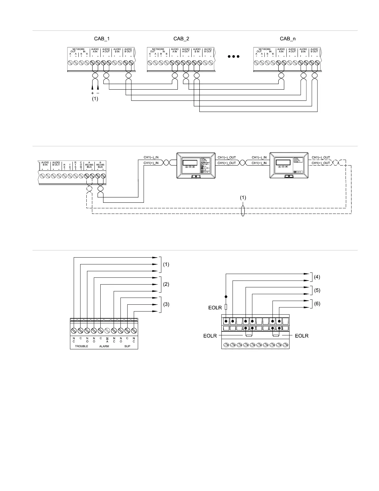
Figure 7: Class A digital audio riser wiring (TB5)
(1) Primary 3X-PMI audio data
Figure 8: RS-485 bus wiring for remote annunciators (TB5)
(1) Class A only
Figure 9: Common relay wiring (TB4)
Legend
(1) Trouble circuit
(2) Alarm circuit
(3) Supervisory circuit
(4) External trouble input circuit
(5) External alarm input circuit
(6) External supervisory input circuit
Notes
• Common relay wiring is unsupervised and power-limited only when connected to a power-limited source.
• For common relay wiring, the end-of-line resistor (EOLR) is determined by the initiating device circuit requirements.
• Common trouble relay operation does not include AC trouble delay functionality. As such, it cannot be used for reporting AC troubles off
premises. To report AC troubles off premises, use a 3-MODCOM Modem Communicator Module.