P/N 3101773-EN • REV 04 • ISS 05AUG13 3 / 8
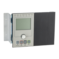
Figure 2: Installing the SFS1-CPU
(1) Electronics chassis
(
2) Plungers (4X)
3) Option card guide
(4) Data ribbon cable (P/N 250189-01)
(5) Power supply cable (P/N 250187-01)
(
6) Exploded view of connectors J1 and J2 on the PS10-4B
7) PS10-4B power supply protective cage is installed here for ULC applications
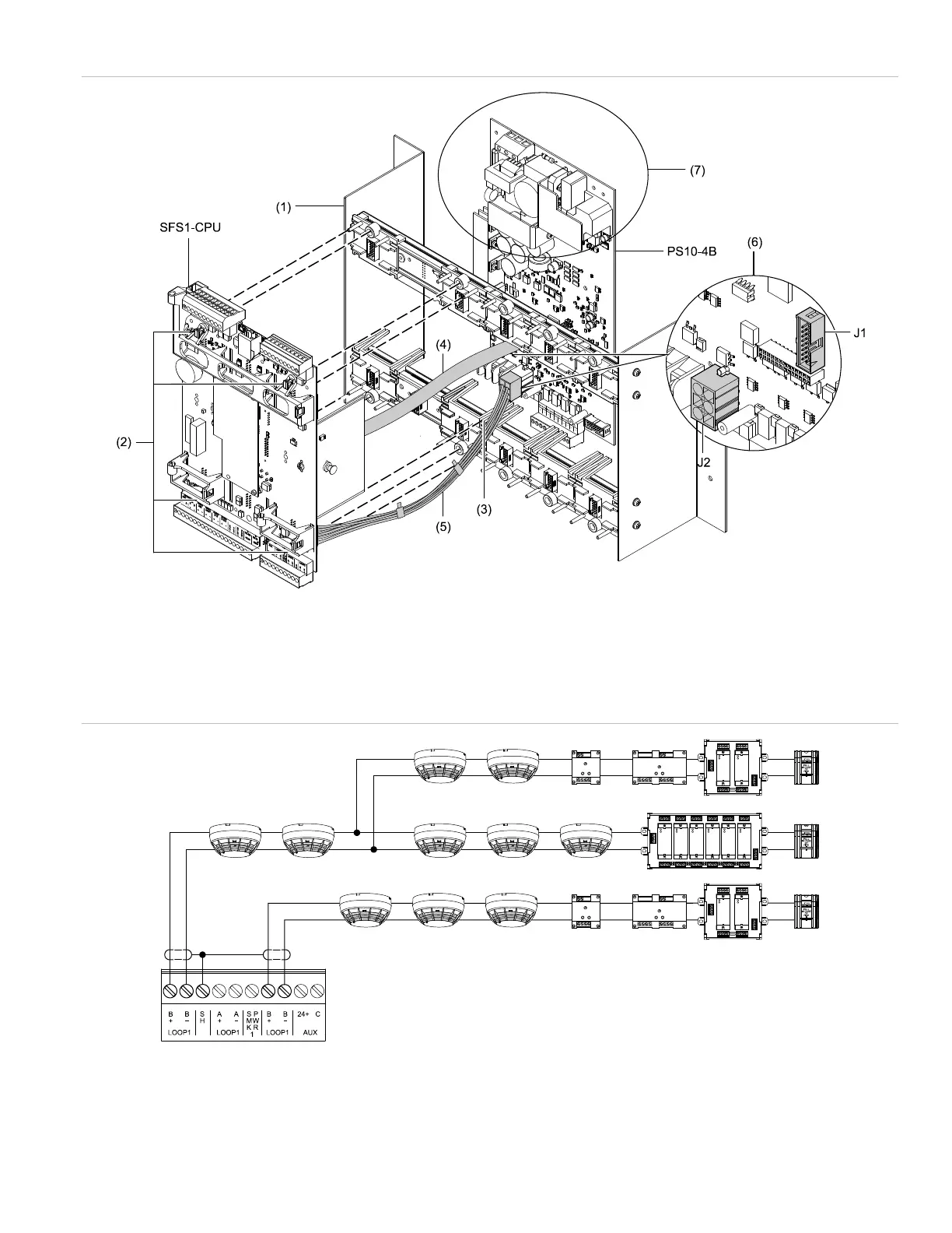
Figure 3: Class B SLC wiring (TB1/TB2)