P/N 3101773-EN • REV 04 • ISS 05AUG13 7 / 8
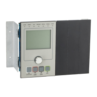
Figure 13: Power-limited and nonpower-limited wiring
(1) Nonpower-limited wiring area
(2) Power-limited wiring area
(3) Battery area
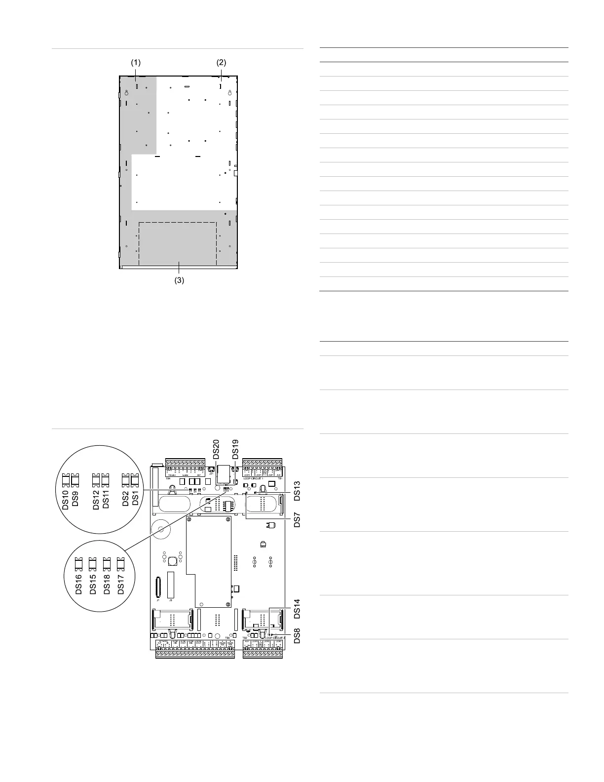
LED indicators
The SFS1-CPU main board provides several LEDs that
indicate activity on a communication path. See Figure 14 for
the LED locations on the main board and Table 2 for LED
descriptions.
Figure 14: SFS1-CPU LEDs
Table 2: SFS1-CPU LED descriptions
Descriptions
Option card RX activity
Option card TX activity
Loop 1 Class A activity
Loop 2 Class A activity
Network data RX Class B activity
Network data TX Class B activity
Network data RX Class A activity
Network data TX Class A activity
Loop 1 Class B activity
Loop 2 Class B activity
Remote annunciator data right TX activity
Remote annunciator data right RX activity
Remote annunciator data left TX activity
Remote annunciator data left RX activity
Ethernet link activity
Ethernet collision activity
Specifications
24 VDC
Standby
Alarm
115 mA
115 mA
Quantity
Type
Rating
3 (alarm, supervisory, trouble)
Form C
30 VDC at 1.0 A, 1.0 PF
Type
Voltage
Current
Regulated and power-limited
24 VDC nom., continuous or resettable
1.0 A each circuit, 1.0 A total
Length
Resistance
Capacitance
20 ft. (6 m) max.
13 Ω max.
0.7 µF max.
Remote annunciator circuit
Length
Resistance
Capacitance
Compatible devices
Twisted-pair, 6 twists/ft. min.
4,000 ft. (1,219 m) max.
90 Ω max.
0.3 µF max.
RLCD-C, RLCD, RLED-C, GCI
-485 network
See the 3X-NET8 RS-
Card Installation Sheet (P/N 3101768-
or 3X-NET RS-485 Network Option Card
Installation Sheet (P/N 3101771-ML)
Fiber optic network
communication
See the 3X-FIB8 Fiber Network Option
Module Installation Sheet
(P/N 3101769-ML) or 3X-FIB Fiber
Network Option Module Installation Sheet
(P/N 3101971-ML)
See the 3X-ETH1 Ethernet Adapter Card
Installation Sheet (P/N 3101775-ML)