10
Virtual Driver’s Cab
„Write Sound Files“: This button enables you to write the sound
files contained in the project file onto the decoder connected
to the LokProgrammer. Click „Continue“ in the window that
opens first in order to write the sound files. Depending on the
size of the file and the size of the memory this may take up to
10 minutes.
Please bear in mind, that you have to write the CVs once
again, if you have made any changes.
„Write Address Allocations“. Any data contained in the project
file regarding the allocation (e.g.: sound slots to function buttons)
will be written onto the decoder.
The following fields next to the tool bar are of purely informa-
tive character:
This field shows the decoder type connected to the
LokProgrammer. In this example it is a LokSound decoder version
3.5. Of course you can work with any LokSound decoders (as
from LokSound 2 upwards), as well as LokPilot-types in DCC
(NMRA), Motorola®, M4 and Selectrix ®.
This field shows the size of the sound memory of the decoder.
Depending on the type this could be 1Mbit, 2Mbit, 4 Mbit
(LokSound 2), 8Mbit or 16Mbit (LokSound 3.5).
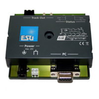
6. Virtual driver’s cab
With the aid of the virtual cab you can test decoders. You can
run the locomotive and trigger all functions. Therefore you can
test run your locomotive on the programming track with the
LokProgrammer.
Fig.13.: Virtual Driver’s Cab
There are some limitations, though: the LokProgrammer limits
the permitted current to about 400 mA. Should the motor of
the locomotive draw a higher current then the over current
protection will be triggered and the power to the programming
track will be shut off. This is indicated by the blinking yellow
LED on the LokProgrammer. In this case deactivate the virtual
cab and then turn it on again.
All other functions in this register are self explanatory: You can
enter the address and the number of speed steps. Please make
sure that the speed steps matches the ones set on the
LokProgrammer.
The LokProgrammer can run locomotives in DCC format, as
from version 2.5 also in the Motorola® format. Due to the
hardware the LokProgrammer cannot handle M4. Test your
M4 projects in the Motorola® format.
Please check that your programming track is fully isolated from
the mainline of your layout prior to turning on the virtual cab.
Should there be any electrical bridge it could damage the
LokProgrammer (also refer to 2.2.)!
Activate the locomotive for the test run by clicking the field
„Activate Cab“.
Control the speed of the locomotive with the slide throttle.
Clicking into the appropriate fields turns functions on and off.
Up to function F12 you may also press the numbers on your
computer keyboard.
Please bear in mind that running a locomotive with the
LokProgrammer cannot and should not substitute a command
station: due to the limited power of the power pack you will
not be able to run more than one locomotive at any one time.
The virtual cab simply gives you the opportunity to quickly test
run your locomotive.
7. Edit CVs
In the register „Edit CVs“ you can read or write individual CVs.
Select the register „Read / Write CVs“.
Fig.14.: Subwindow „Edit CVs“
Read a CV:
• Enter the number of the CV you want to read in the upper
data entry field.
• Press the button „Read CVs“.
• The result will be shown in binary and decimal format.
Write a CV:
• Enter the number of the CV you want to write in the field at
the top.
• Write the new value of the CV in the lower data entry field.
• Click onto the button „Write CVs“.
• The CV will be overwritten with the new value.
You can also read out the manufacturer’s code. Simply click
onto „Read Data“.
Please bear in mind that any changes made here are not
automatically displayed under „Decoder“. You must first read
out the decoder data (also refer to chapter 5.3).
You will find a comprehensive list of CVs in 13.1.
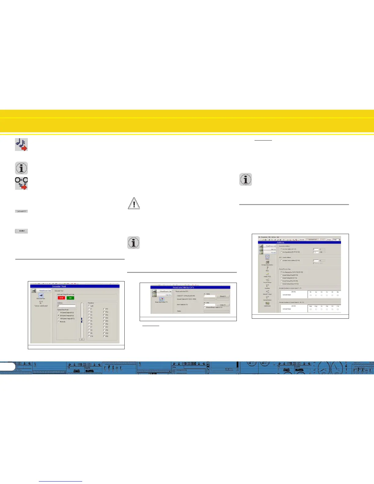
8. The „decoder“ register
All settings regarding the motor control part of the decoder
are handled in the „Decoder“ register. Please note that this
register is initially empty when you start the program. Info will
only be displayed in this field after you have generated a new
project, opened an existing project or read out a decoder.
Projects are an image of all data stored on a decoder.
Fig.15.: The „Decoder“ register
The buttons that let you go to the different options are on the
left of the screen. Besides movement and sound behaviour you
can adjust specific settings such as brake mode, address, etc.
On the following pages we will explain the parameters and
options.