5 Installation
Explanation of symbols
The jumper colours enable visual assignment of
the functions and have no technical relevance.
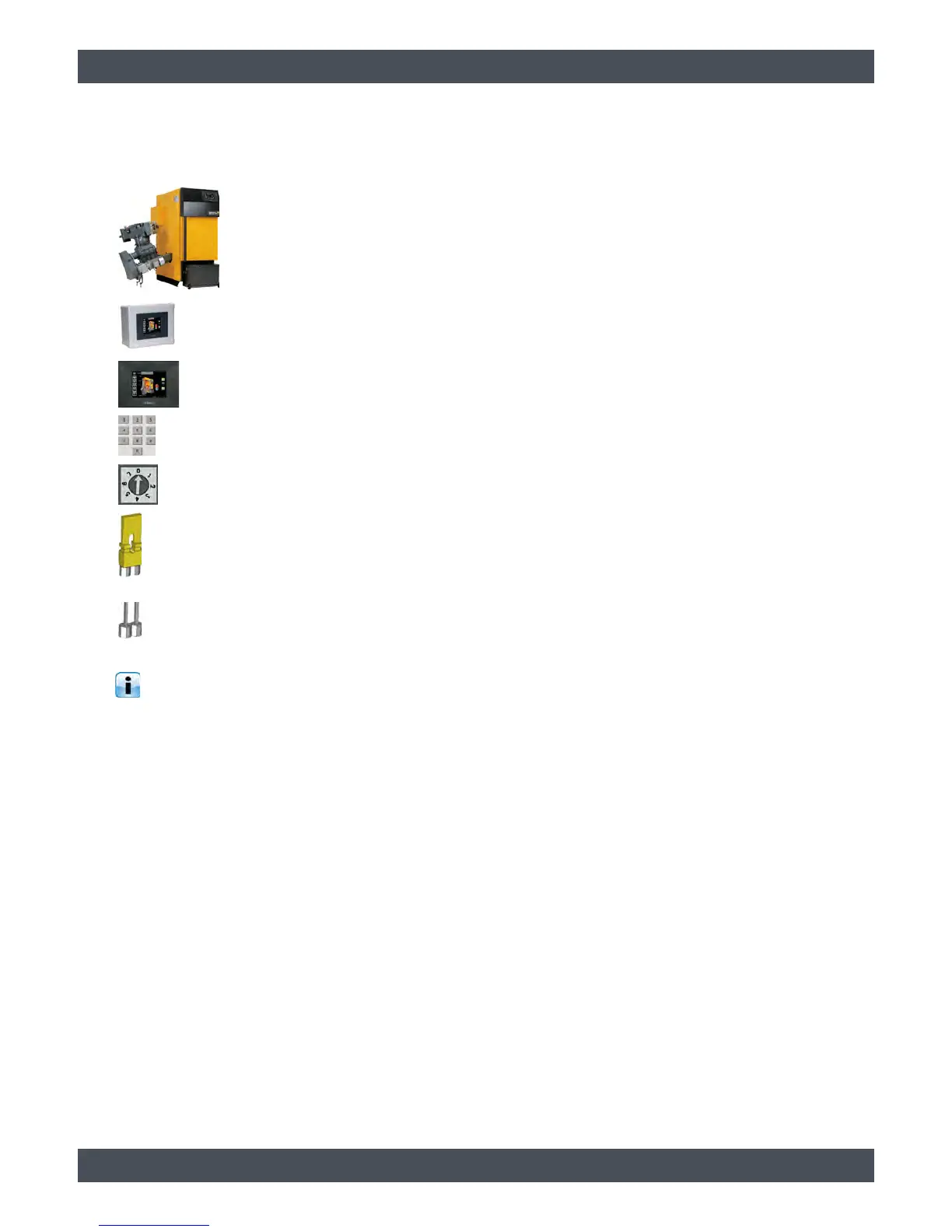
HACK wood chip boiler
T2-BT control extension with
integrated ETAtouch control panel
ETAtouch control panel BE-P
Node number of the BE-P
Node switch on the circuit board
The circuit board is located at the
end of the CAN bus connection
A yellow jumper must be set.
The circuit board is within the CAN
bus connection.
No yellow jumper may be on the
circuit board.