8.0 COMMISSIONING THE PUMP AND CALIBRATION
8.1 HD-PH (COMMISSIONING THE PUMP)
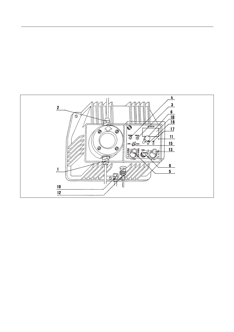
1 Suction hose connector nipple 11 Control panel
2 Delivery hose connector nipple 12 Electrode cable connector
3 Stroke Led (red) 13 Set-point selector “pH set”
4 Power Led (green) 15 Acid/Alk switch
5Injection frequency regulation knob 16 Calibration trimmer
“pH/mV” 17 Calibration trimmer “
∆
0 “
6Front cover fixing screw 18 Display
9 Fuse
10 Supply cable
a. Install the metering pump as described in Chapter 6.0 “PUMP INSTALLATION
”.
b. Place the electrode in the electrode holder.
c. Connect the electrode to the metering pump by means of the male BNC connec-
tor (12), rotating it through 90°C.
d. Position the "pH set" knob (13) to the desired pH value, bearing in mind that the
scale dimensions are such as to give rise to a possible discordance between the
intervention point and the reading on the display (18). For example, if the "pH
set" knob is set to pH 7 and one then notes that pump has not yet come into
operation at pH 7.2, it would be desirable to carry out a check and, if necessary,
correct the set point by adjusting the "pH set" knob.
e. Use the "ACID/ALK" switch (15) to select the required type of intervention (acid
or alkaline). Example: If the intervention point is set at pH 9 and an acidification
is required, set the switch to ACID. The pump will then start dosing the addi-
tive every time the pH rises above 9. If it is desired to alkalinize the system, set
the switch to
ALK, in which case the pump will come into operation every time
the pH drops below 9
.
f. Use the FLOW knob (5) to set the number of injections per minute, reducing or
increasing the pump discharge according to requirements. In this connection it
36
ENG
fig.9