8
ENGLISH
INSTALLATION
Install the pump in a dry area away from heat sources at a
maximum ambient temperature of 40 °C, while the minimum
operating temperature depends on the liquid to be dosed which
must always remain in the uid state.
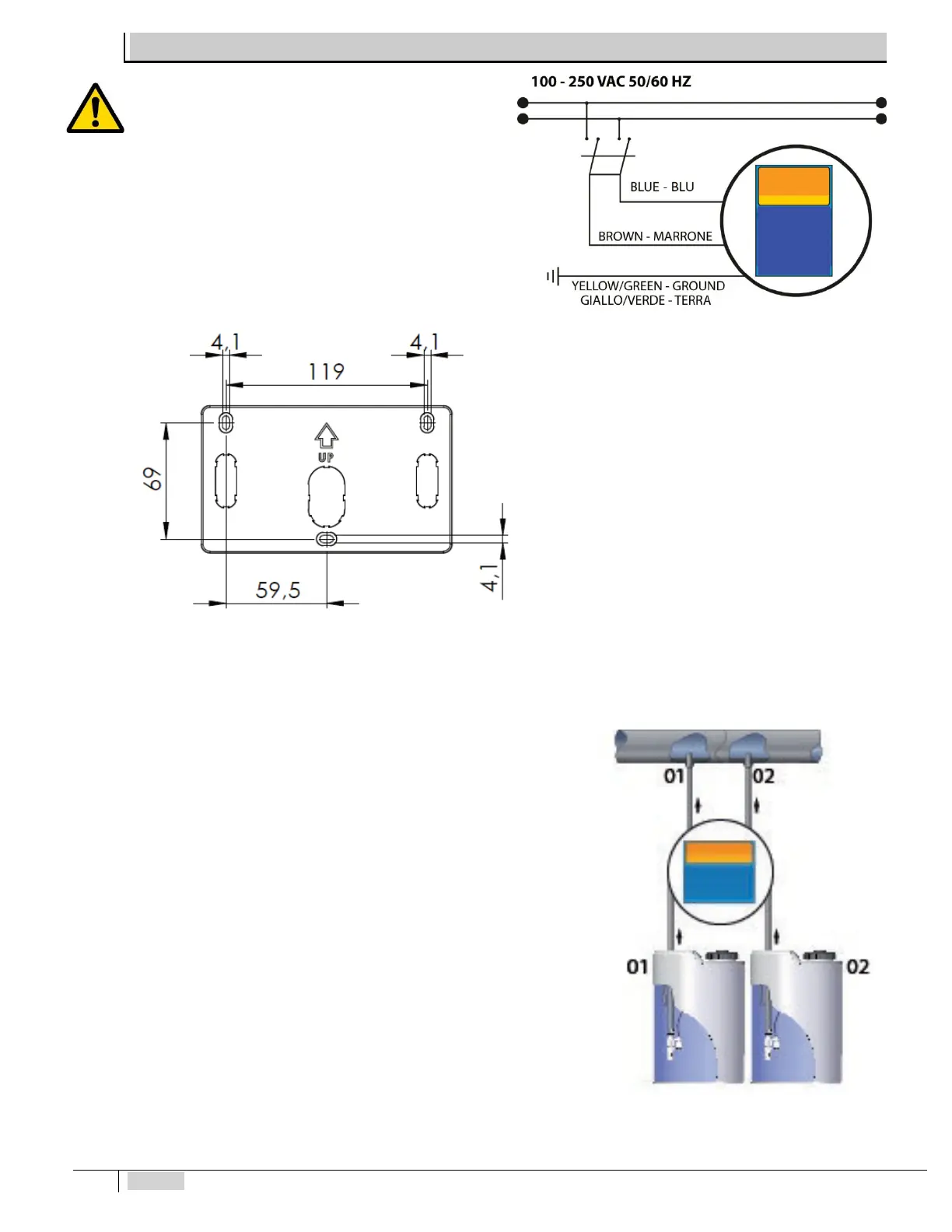
Comply with standards in force in the different countries
regarding the electrical installation (Fig. 2). If the power cord
does not have a plug, the device must be connected to the
mains by means of an omnipolar disconnecting switch with at
least 3 mm between the contacts. All the power circuits must
be interrupted before accessing the connection devices.
Fig. 3 – Electrical connection
The device is supplied with a bracket to x it to the wall
and relative plugs for masonry walls. Always use a plug
appropriate to the available support. The layout of the
holes to be drilled on the support is displayed in
Fig. 1 – Views and dimensions – peristaltic version
Fig. 2 – Views and dimensions –
electromagnetic version
Fig. 4 – Drilling support bracket
Position the pump as in the gure, considering that it must be secured both
below and above the level of the liquid to be dosed within a maximum limit of 2
m. The injection points must always be higher than the liquid to be injected. For
liquids which let out aggressive fumes, do not install the pump above the tanks
unless they are watertight.
Insert the tubes all the way on the relative tapered couplings and block
them with the specic ring nuts. Donot make elbowson the supplyand suction
pipe. Apply a 3/8” gas female tting on the piping of the plant to be treated, at the
most suitable point to inject the product to be dosed. This tting is not included in
the supply. Screw the injection valve in the tting using Teflon® as a gasket.
Connect the tube to the tapered coupling of the injection valve and block it with
the specic ring nut. The injection valve is also a check valve.
Fig. 5 – Standard installation