ENGLISH
11
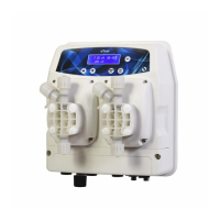
Left side terminal block J16
Fig. 9 – LEFT terminal block J16
No. Description
1 Relay L1 NO
2 Relay L1 NC
3 Relay L1 Common
4 Relay L2 NO
5 Relay L2 NC
6 Relay L2 Common
7 Relay L3 NO
8 Relay L3 NC
9 Relay L3 Common
10
Not connected
11
12
13 Relay L5 NO
Alarm
14 Relay L5 NC
15 Relay L5 Common
Terminals 9-10 (proximity sensor) and 11-12 (external command) of the RIGHT terminal block called “J17” are short-
circuited with removable jumpers. The default triggering mode for these input is set at NO (normally open). To leave the behaviour of
the device unchanged, the jumpers can be removed and switched to NC (normally closed). For the operating modes, see the chapter
on settings of the external inputs.
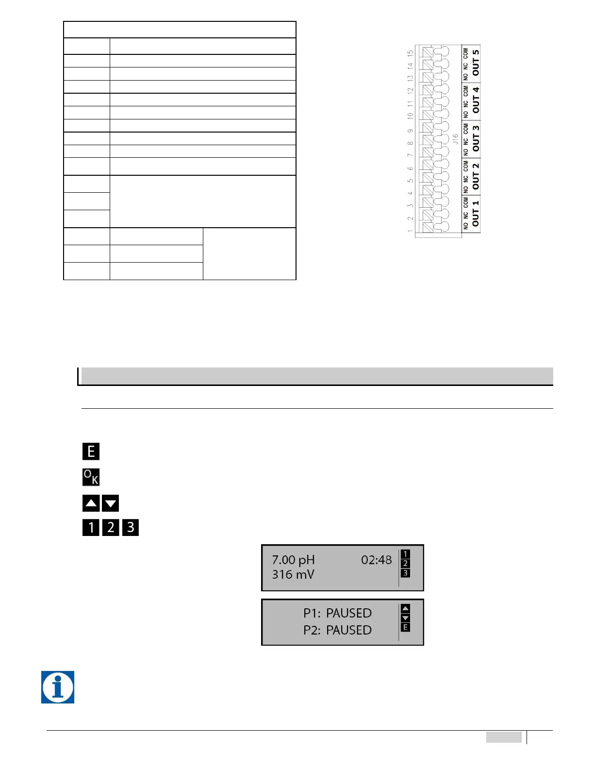
DESCRIPTION OF THE SCREEN
Acce ss to pr ob e sett ing, configu ra ti on and c alibrat io n menus
While browsing the different menu items on the right side of the screen, a series of icons are enabled indicating which keys can
be pressed in that particular context.
you may press the MENU/ESC key
you may press the CAL/OK key
you may press the ARROW keys
In measuring mode, when icons 1, 2, 3 are lit it means that the relative relay is activated.
Instrument screen MEASURING
Instrument screen in PAUSE
When the instrument is switched on, it stores the prior condition, PAUSE OR MEASURING.