10
ENGLISH
The probe connectors are located at the bottom of the device as shown in
Fig. 7 – Opening terminal board cover and position of probe connectors
. Set-points 1 and 2 are always matched respectively to measuring channels 1 and 2 on all eTwin pump models and
versions.
Once the cables are connected, close the cover and delicately pull any extra cable out through the cable glands. ATTENTION:
tighten the gasket as much as possible but not excessively so as not to damage the plastic screws.
The following table shows the allocations of measuring channels 1 and 2 according to your eTwin version.
Measurement - Version
pH - Rx Chlorine - pH pH - pH
Measurement 1 pH Chlorine pH
Measurement 2 Rx pH pH
Table 1 -Conguration of measurement channels of different eTwin versions
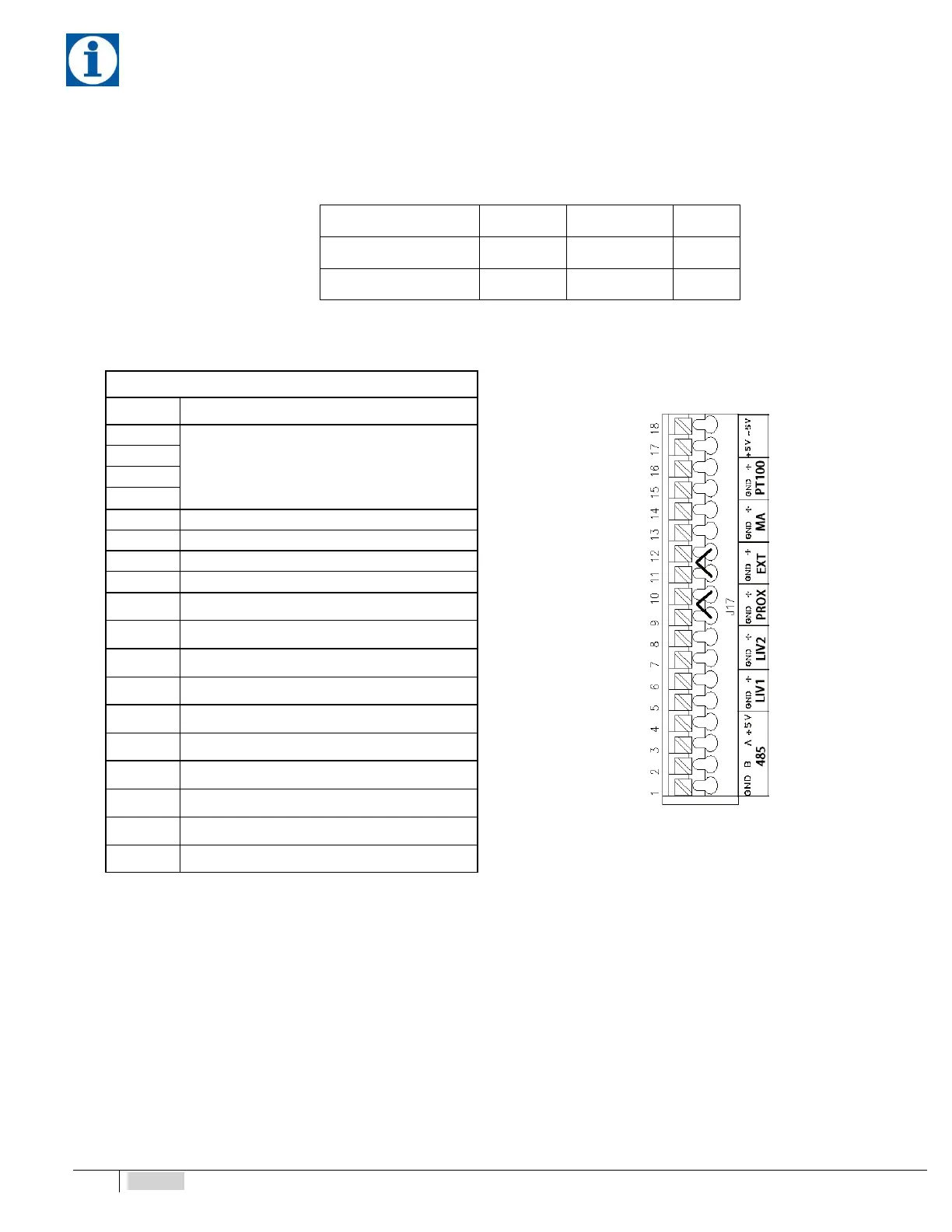
Right side terminal block J17
Fig. 8 – RIGHT terminal block J17
No. Description
1
RS485 (not enabled)
2
3
4
5 Pump 1 Level Probe Input (-)
6 Pump 1 Level Probe Input (+)
7 Pump 2 Level Probe Input (-)
8 Pump 2 Level Probe Input (+)
9 Proximity Sensor Input (-)
10 Proximity Sensor Input (+)
11 External command (-)
12 External command (+)
13 mA output (-)
14 mA output (+)
15 PT100 input (-)
16 PT100 input (+)
17 +5V power supply. Chlorine pot. probe
18 +5V power supply. Chlorine pot. probe