ENGLISH
9
ETWIN
Control P an el
The following gure depicts the control panel with the description of the functions of the different keys.
1 Increase values button
2 Decrease values button
3 MENU - ESC button
4
Calibration (CAL) of
instrument and OK
conrmation button
5
Set-point display and
setting button
Fig. 6 – Control Panel 6 Digital screen
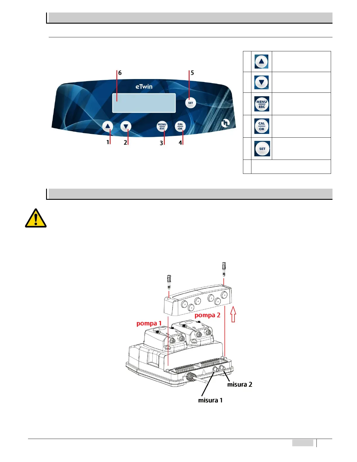
DIAGRAM OF THE ELECTRICAL CONNECTIONS
To connect the accessories and peripheral devices to the pump, remove the front cover, acting on the two plastic screws on the
sides of the cover with a at headed 5mm (at least) screwdriver to reach the terminal board.
The terminal board consists of spring terminals for quick coupling of the wires. Press the square “slotted” pin with a small at
headed screwdriver and insert the stripped wire in the corresponding terminal. ATTENTION: exert slight pressure on the spring pin
to avoid irreparably damaging the terminal board.
Pass the cables through the rubber cable glands on the wall of the cover, using a screwdriver to remove the thin internal closing
septum. Pay attention to perforation of the cable gland and wear appropriate protective equipment (gloves).
Fig. 7 – Opening terminal board cover and position of probe connectors